Model a Simple Link
Mechanical links are common building blocks in linkages, mechanisms, and machines. In this example, you learn how to model a simple mechanical link using Simscape™ Multibody™. For simplicity, the model assumes the link has a brick shape and two end frames.
Build Model
At the MATLAB® command line, enter
smnew. A Simscape Multibody model template with commonly used blocks opens.Delete the Simulink-PS Converter, PS-Simulink Converter, and Scope blocks because they are not used in this example.
Show the names of the Rigid Transform and Brick Solid blocks if they are not shown already. Right-click the block and select Format > Show Block Name > On.
Duplicate the Rigid Transform block to add a second end frame to the link.
Flip the Rigid Transform1 block so that you can connect the B ports of two Rigid Transform blocks to each other and the Brick Solid block.
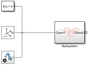
Connect the remaining blocks like the following figure.
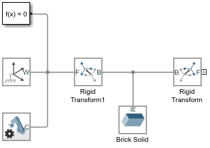
In the Brick Solid dialog box, specify the following parameters. These parameters define the simple link's physical properties, such as shape, mass, and appearance.
Parameter Value Units Geometry > Dimensions [L W H]cmInertia > Density rhokg/m^3Graphic > Visual Properties > Diffuse Color rgbNot applicable In the Rigid Transform blocks, specify the following parameters. These parameters specify the locations of two end frames on the simple link. After you enter the parameters, the Brick Solid and Rigid Transform blocks will be highlighted in red because you have not defined the variables yet. This issue will be solved after inputting all the numerical values for the parameters, which will be described in the following section.
Parameter Rigid Transform1 Rigid Transform Units Translation > Method Standard AxisStandard AxisNot applicable Translation > Axis -X+XNot applicable Translation > Offset L/2L/2cm
Generate Subsystem
You can build a complex multibody system using several simple models, such as a simple link model. The physical parameters of these simple models usually need to be adjusted to fit different design requirements. To simplify the parameter adjusting process, you can create Subsystem blocks for these simple models. A Subsystem block enables you to update many parameters in a single place—the Subsystem block dialog box. In this section, you learn how to create a Subsystem block for the simple link model.
Select the Brick Solid block and the two Rigid Transform blocks by holding shift and clicking the blocks.
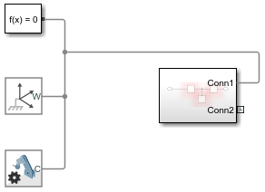
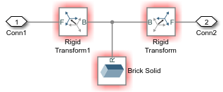
Right-click one of the selected blocks and select Create Subsystem from Selection. Simulink® adds a new Subsystem block that contains the Brick Solid and Rigid Transform blocks.
Double-click the Subsystem box. A new tab displays the children blocks of the Subsystem block. Double-click the Conn1 and set Port location on parent subsystem to left. Click OK to apply the change and navigate back to the parent model by clicking the up arrow button next to the Subsystem tab.
Adjust the size and location of the Subsystem block as shown in the figure.
Right-click the Subsystem block and select Mask > Create Mask. The Mask Editor window opens, where you can define the MATLAB variables that you entered in the Brick Solid and Rigid Transform block dialog boxes.
Click the Parameters & Dialog tab and click Edit
 five times to create five
Edit fields. In the Edit
fields, specify the following parameters and click
OK. The Prompt property
specifies the names of the parameters that you can enter in the
Subsystem block parameter window. The Name property
specifies their corresponding MATLAB variables.
five times to create five
Edit fields. In the Edit
fields, specify the following parameters and click
OK. The Prompt property
specifies the names of the parameters that you can enter in the
Subsystem block parameter window. The Name property
specifies their corresponding MATLAB variables.Prompt Name Length (cm)LWidth (cm)WThickness (cm)HDensity (kg/m^3)rhoColor [R G B]rgbDouble-click the Subsystem block. Enter the following numerical values in the Subsystem Block Parameters window and click OK. These values specify the shape of Brick Solid and the location of Rigid Transform blocks.
Parameter Value Length (cm) 20Width (cm) 1Thickness (cm) 1Density (kg/m^3) 2700Color [R G B] [0.25 0.40 0.70]
Visualize Model
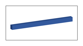
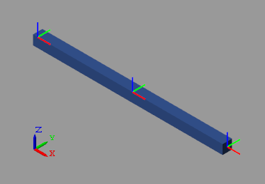
Run the model. The Multibody Explorer opens with a
front view of the simple link model. To see the 3D view of the model, click the
isometric view button ![]() . To view the frames in the model, in the
Multibody Explorer tab, select View > Show Frames in the Multibody Explorer menu bar.
. To view the frames in the model, in the
Multibody Explorer tab, select View > Show Frames in the Multibody Explorer menu bar.
Save Custom Block
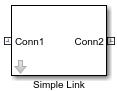
To reuse this Subsystem block in other examples, such as the Model a Simple Pendulum example, you can change its name to Simple Link and save it as a custom block. For more information, see Design and Create a Custom Block.
Simple Link Custom Block
See Also
Brick Solid | PS-Simulink Converter | Rigid Transform | Scope | Simulink-PS Converter