Specify Joint Motion in Planar Manipulator Model
This example shows how to specify the trajectory of the end effector of a planar manipulator and measure the required actuator torques of the manipulator joints in the multibody dynamics model. For more information about multibody dynamics simulations, see Multibody Dynamics.
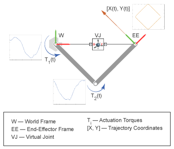
In this example, you specify the time-varying trajectory coordinates of the end-effector frame with respect to the world frame by using a 6-DOF Joint block. This block provides the requisite degrees of freedom between the two frames. In this model, the 6-DOF Joint block does not act as a physical connection.
During the simulation, the end effector traces the specified square pattern and the revolute joints compute the required actuator torques.
Add Virtual Joint
At the MATLAB® command prompt, enter
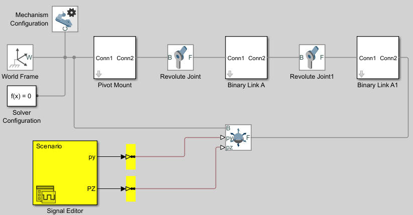
openExample("sm/DocDoublePendulumModelExample")to open the model. For instructions on how to create this multibody dynamics model, see Model an Open-Loop Kinematic Chain.Add a 6-DOF Joint block to the model and connect the blocks as shown in the figure.
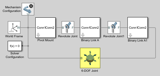
In this model, the 6-DOF Joint block works as a virtual connection between the world frame and the end-effector frame. The block uses the position inputs to specify the trajectory of the end-effector frame with respect to world frame. Ensure that the base frame of the 6-DOF Joint block connects to the world frame and the follower frame connects to the end-effector frame.
Prescribe Motion Inputs
Double-click the 6-DOF Joint block to open the block dialog box and specify these parameters.
Parameter Select Y Prismatic Primitive (Py) > Actuation > Motion Provided by InputZ Prismatic Primitive (Pz) > Actuation > Motion Provided by InputThe block exposes ports py and pz.
Add two Simulink-PS Converter blocks and one Signal Editor block to the model.
Use the Signal Editor block to specify the position inputs.
Double-click the Signal Editor block to open the dialog box.
Under Signal properties, click the Launch Signal Editor button
 to open the Signal Editor window.
In the left pane, expand Scenario, rename the
signal 1topy, select the Plot/Edit check box, and edit the data as shown in the image.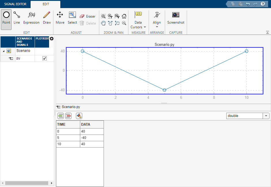
In the left pane, right-click Scenario, select Insert > Signal, rename the new signal to
pz, select the Plot/Edit check box, and edit data as shown in the image.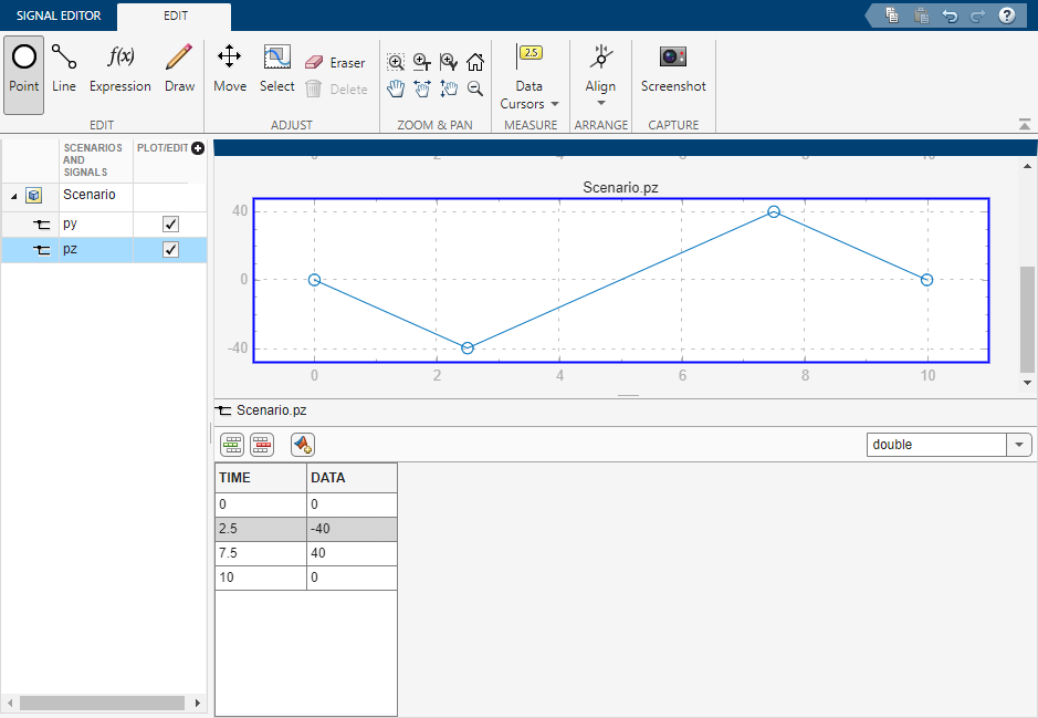
In the Signal Editor tab, click Save to save the data to a MAT file. Close the Signal Editor window.
In the dialog box, under Signal properties, set Active signal to
pyand select Interpolate data. Then, set Active signal topzand select Interpolate data. Click Apply and OK.
Use the Simulink-PS Converter blocks to convert Simulink® signals into physical signals.
In the two Simulink-PS Converter blocks, specify these parameters.
Parameter Value Units > Input signal unit cmInput Handling > Filtering and derivatives Filter input, derivatives calculatedInput Handling > Input filtering order Second-order filteringInput Handling > Input filtering time constant (in seconds) 0.1Note that a small time filtering constant can slow a simulation significantly. For most Simscape™ Multibody™ models, a value of 0.1 seconds often provides a sufficient balance between simulation time and accuracy.
Connect the blocks as shown in the figure.
Sense Joint Actuation Torques
In the two Revolute Joint blocks, set these parameters:
Parameter Setting Actuation > Torque Automatically ComputedSensing > Actuator Torque Selected Note
Simscape Multibody requires the number of joint primitive degrees of freedom with motion inputs to be equal to the number of joint primitive degrees of freedom with automatically computed joint actuator forces and torques. If the model does not meet this condition, the simulation fails with an error.
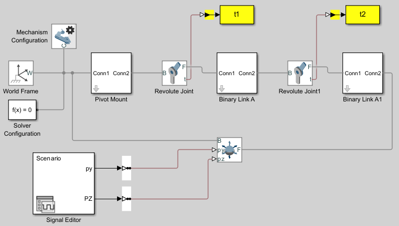
Add two PS-Simulink Converter blocks and two To Workspace blocks to the model.
In the PS-Simulink Converter blocks, set Vector format to
1-Darray. The PS-Simulink Converter blocks convert the physical signal outputs into Simulink signals.In the two To Workspace blocks, specify the Variable name parameter as
t1andt2, respectively.Connect the blocks as shown in the figure.
Simulate Model
If you run the simulation, Simulink fails with an error.
Note
Simscape Multibody requires any closed kinematic loop to contain at least one joint block without motion inputs or automatically computed actuator forces or torques.
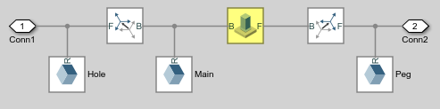
To solve the error, add a Weld Joint block to the Binary Link A subsystem and connect the blocks as shown in the figure.
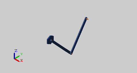
Run the simulation again. Multibody Explorer opens with a dynamic 3-D display of the planar manipulator model.
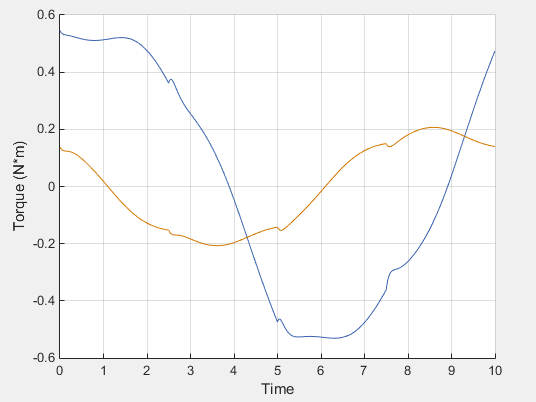
Plot the computed actuation torques that act at the two revolute joints in the linkage. At the MATLAB command line, enter:
figure;
hold on;
plot(t1.time, t1.data, 'color', [60 100 175]/255);
plot(t2.time, t2.data, 'color', [210 120 0]/255);
xlabel('Time');
ylabel('Torque (N*m)');
grid on;