Map Tasks and Peripherals Using Hardware Mapping
This topic shows how to use the Hardware Mapping tool to configure software tasks and peripherals on an Infineon AURIX™ TC4x Microcontroller.
Using Hardware Mapping tool, you can:
Configure the peripherals by setting the hardware specific parameters. The available parameters depend on the selected hardware board for the model and the peripheral blocks used in the model.
Map the tasks in your software model to the available event sources and interrupts. The sources of events or interrupts depend on the choice of hardware board and peripherals available in the model.
Configure Hardware Mapping Tool
In this section you will learn how to configure a Hardware Mapping tool and create a model with PWM and Hardware Interrupt block from the SoC Blockset™ Support Package for Infineon® AURIX Microcontrollers.
Enter
at the MATLAB® prompt to open the Simulink® Library Browser.slLibraryBrowser
In the Simulink Library Browser, expand the SoC Blockset Support Package for Infineon AURIX Microcontrollers node, and then expand the AURIX TC4x.

Drag and drop two PWM blocks and Hardware Interrupt block in a new Simulink model.
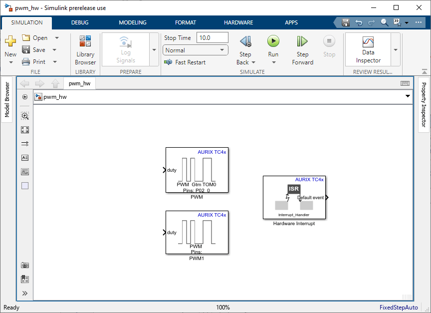
Save the Model.
Double-click the PWM and Hardware Interrupt blocks to review the block mask, which contains a description of the block parameters to configure the associated pins.
In your Simulink model, press Ctrl+E or click Modeling > Model Settings to open Configuration Parameters dialog box.
Select the Hardware Implementation pane and select the required Infineon hardware board from the Hardware board parameter list at the top and also select the required core from the Processing Unit parameter list.

Click Apply and OK.
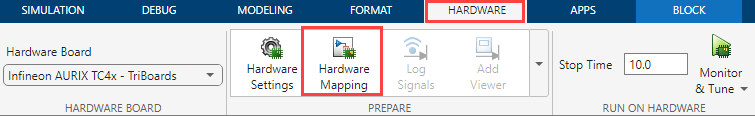
A Hardware Mapping tool in the Hardware tab becomes visible in Simulink toolstrip.
Configure Peripherals and Tasks
Click Hardware Mapping to open the Hardware Mapping tool.
Complete the following steps in Hardware Mapping tool.
You can configure the peripheral by setting hardware specific parameters. To set the peripheral, select the peripheral in Browser > Peripherals >
Peripheral group name> Peripheral block name.In the right pane, click the relevant block tab and modify its settings. The values are applied to the hardware peripheral when deployed to the hardware board. The available parameters depend on the selected hardware board for the model and the selected peripheral block.

Map tasks in your software model to the available event sources and interrupts:
Manually select the task in Browser > Tasks >
CPU name. Select the desired event or interrupt. source. Click the Apply Changes button in the toolstrip.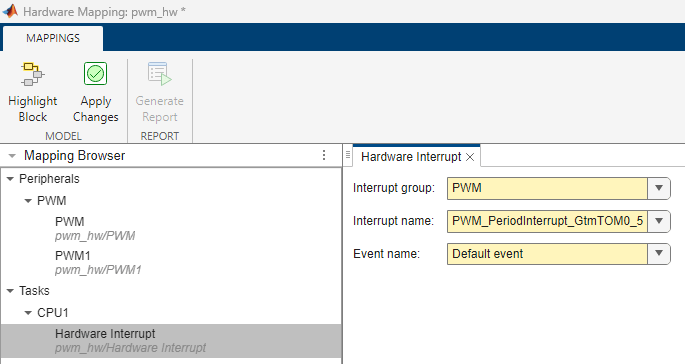
From this demonstration, you can verify that the event
PWM_PeriodInterrupt_GtmTOM0_5is available as this is enabled in the PWM peripheral block as shown in the peripheral block name.
Note
The sources of events or interrupts depend on the choice of hardware board and peripherals available in the model.
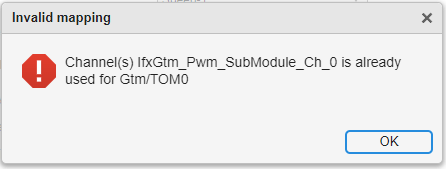
After configuring all the parameters for peripherals in Hardware Mapping, click Apply Changes.
Check for any conflicts between tasks. For example,
Click Generate Report to view the hardware mapping summary report. The hardware mapping summary report with all the peripheral configurations are generated in a web page and saved in the following location:
file:///C:/Users/<username>/AppData/Local/Temp/html/SummaryReport

You can also select a web site from the following list:
Americas
- América Latina (Español)
- Canada (English)
- United States (English)
Europe
- Belgium (English)
- Denmark (English)
- Deutschland (Deutsch)
- España (Español)
- Finland (English)
- France (Français)
- Ireland (English)
- Italia (Italiano)
- Luxembourg (English)
- Netherlands (English)
- Norway (English)
- Österreich (Deutsch)
- Portugal (English)
- Sweden (English)
- Switzerland
- United Kingdom (English)