Model DC-DC Buck Converter Using Infineon AURIX
This example shows how to model a DC-DC buck converter application that converts the voltage from 48 V to 12 V using the Infineon® AURIX™ TC4x microcontroller.
Using the model in this example, you can design a buck converter using the per-unit-based voltage mode control (VMC) technique. The model sets the inductance L and smoothing capacitor C as per the input and output specifications mentioned in the tc4x_DCDCBuckConverter_data.m file. You can change these specifications as per your requirements in base workspace and rerun the model to design the buck converter.
Introduction
In this example, you will learn more about the typical challenges associated with power conversion simulation:
Modeling the analog circuit behavior of the buck converter circuit.
Modeling the timing behavior of PWM output and ADC sampling on an MCU.
The example addresses these challenges using Embedded Coder® and Simscape™.
Required Hardware
Infineon AURIX TC4x - TriBoards
Model
Open the IfxDCDCBuckConverter model.

The ADC Interrupt task contains the feedback control algorithm that executes in response to each ADC conversion event and generates duty cycle values for the PWM block. In simulation mode, this behavior is emulated by function call generator subsystem.
Use the Converter Enable push button to the start the controller. Converter Enable push button enables you to have control over the start of the converter to avoid any controller saturation during the start of the converter. Variant Source and Sink are utilized to separate the simulation and code generation actions.
Model of DC-DC Buck Converter
The BuckConverterPlant subsystem is a Simscape reference model of the analog circuitry of DC-DC Buck converter. To achieve computational efficiency during simulation without impacting the analog behavior of the circuit, the model includes these simplifications:
Voltage and current sensing circuits are simplified as Gain blocks.
MOSFETS are simplified to ideal MOSFETS.
Gate driver is not modeled and its propagation delays are not considered.
Inductor is simplified to a linear inductor.
All parts are modeled with nominal values and tolerances are not considered.
DC supply is assumed to be constant.

The PWM generator is implemented using a sawtooth generator as shown in the image.

Voltage Mode Control on MCU
In this control method the duty cycle of the converter is controlled based on the output voltage of the converter. In the MCU, the output of the plant sampled by the ADC Interface generating an event on each end of conversion. This event triggers the control algorithm that utilizes PI controller logic to modify the duty cycle based on the error voltage.
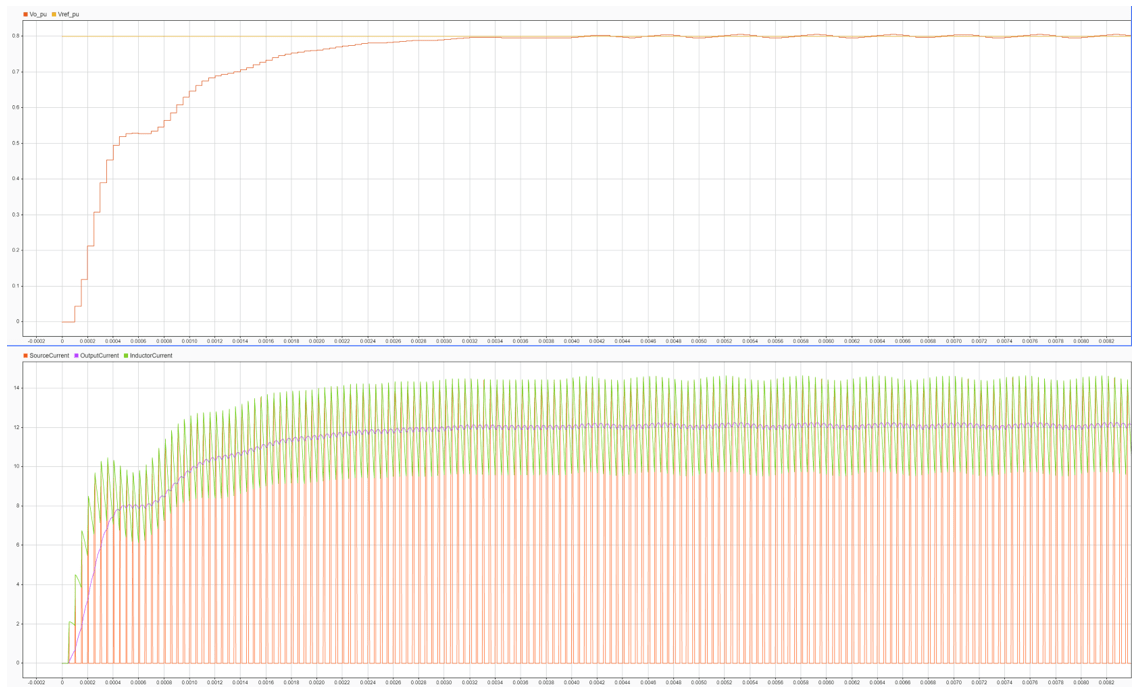
The discrete proportional integral (PI) controller minimizes the error between the reference voltage and the output voltage by controlling the duty cycle of the converter. The duty cycle of the PI controller is limited to 80% of the PWM time period there by limiting the output voltage to 0.8*Vin.

Results
These plots show the results from a buck converter that converts power supply from 48 V to 12 V using a 12-W converter. You can edit the input and output power specifications in the tc4x_DCDCBuckConverter_data.m file as per requirements and verify the results. Set the base voltage in per units, so that controller does not saturate.
You can also select a web site from the following list:
Americas
- América Latina (Español)
- Canada (English)
- United States (English)
Europe
- Belgium (English)
- Denmark (English)
- Deutschland (Deutsch)
- España (Español)
- Finland (English)
- France (Français)
- Ireland (English)
- Italia (Italiano)
- Luxembourg (English)
- Netherlands (English)
- Norway (English)
- Österreich (Deutsch)
- Portugal (English)
- Sweden (English)
- Switzerland
- United Kingdom (English)