PWM Generator (Pulse Averaging)
(To be removed) Carrier-based PWM generator with pulse averaging
The Specialized Power Systems library will be removed in R2026a. Use the Simscape™ Electrical™ blocks and functions instead. For more information on updating your models, see Upgrade Specialized Power Systems Models to use Simscape Electrical Blocks.

Libraries:
Simscape /
Electrical /
Specialized Power Systems /
Power Electronics /
Power Electronics Control
Description
The PWM Generator (Pulse Averaging) block generates pulses, averaged over the sample time model, to use with these converter blocks when they have a switching function model selected:
Two-quadrant DC/DC Converter block
Full-Bridge Converter block
Two-Level Converter block
Three-Level NPC Converter block
To use an SPS interpolation technique or SPS switching function models, the SPS solver needs to know when a transition from high-to-low or low-to-high occurs within a sample time. The PWM Generator (Pulse Averaging) block can provide the timing for these transitions.
With this pulse-averaging generator (and the SPS switching function converter models), a much higher sample time can be used for the SPS model while maintaining a high-fidelity simulation. Consequently, this generator serves as a virtual FPGA.
This figure illustrates the operation of the generator for a specified carrier
frequency (Fc) of 2 KHz and a duty cycle (D) of
0.8. The model execution time (Ts) is 50 microseconds.
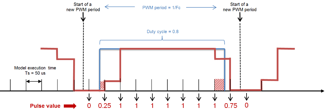
The generator outputs a pulse value using a naturally sampled, carrier-based
modulation technique. If a transition occurs within a sample time, the generator will
output a pulse value representing the time ratio (a value between 0 and 1) for the
on state over the sample time. For example, at the sample time
identified by the first blue arrow, the generator outputs a value of 0.25, which
represents that the pulse entered on at 0.25*Ts seconds (it was
on during 25% of the model execution time). The offset is
represented by the red dashed area. Similarly, at the sample time identified by the
second blue arrow, the generator outputs a value of 0.75, which represents that the
pulse was on during 75% of the model execution time (it entered the off state 0.75*Ts
seconds after the previous sample time).
Ports
Input
Output
Parameters
Extended Capabilities
Version History
Introduced in R2019b