FEM-Parameterized Rotary Actuator
Rotary actuator defined in terms of magnetic flux
Libraries:
Simscape /
Electrical /
Electromechanical /
Mechatronic Actuators
Description
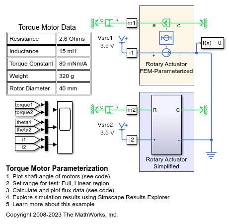
The FEM-Parameterized Rotary Actuator block implements a model of a rotary actuator defined in terms of magnetic flux. Use this block to model custom rotary actuators and motors where magnetic flux depends on both rotor angle and current. You parameterize the block using data from a third-party Finite Element Magnetic (FEM) package.
The block has two options for the electrical equation. The first,
Define in terms of dPhi(i,theta)/dtheta and
                        dPhi(i,theta)/di
, defines the current in terms of partial
derivatives of the magnetic flux (Φ) with respect to rotor angle (θ) and current
(i), the equations for which are:
The second option, Define in terms of Phi(i,theta),
defines the voltage across the component directly in terms of the flux, the
equation for which is:
Numerically, defining the electrical equation in terms of flux partial derivatives is better because the back-emf is piecewise continuous. If using the flux directly, using a finer grid size for current and position will improve results, as will selecting cubic or spline interpolation.
In both cases, you have an option to either directly specify the torque as a function of current and rotor angle, by using the Torque matrix, T(i,theta) parameter, or have the block automatically calculate the torque matrix.
If entering the electromagnetic torque data directly, you can either use data supplied by the finite element magnetic package (which you used to determine the flux) or calculate the torque from the flux with following equation:
See the Solenoid Parameterized with FEM Data example model for an example of how to implement this type of integration in MATLAB®.
Alternatively, the block can automatically calculate the torque matrix from the
flux information that you provide. To select this option, set the
Calculate torque matrix? parameter to
Yes. The torque matrix calculation occurs at
model initialization based on current block flux linkage information. The torque
is calculated by numerically integrating the rate of change of flux linkage with
respect to angle over current, according to the preceding equation. If the
Electrical model parameter is set to
Define in terms of Phi(i,theta), then the block
must first estimate the Flux partial derivative wrt angle,
Phi(i,theta)/dtheta parameter value from the flux linkage data.
When doing this, the block uses the interpolation method specified by the
Interpolation method parameter. Typically, the
Smooth option is most accurate, but the
Linear option is most robust.
You can define Φ and its partial derivatives for just positive, or positive and negative currents. If defining for just positive currents, then the block assumes that Φ(–i,x) = –Φ(i,x). Therefore, if the current vector is positive only:
The first current value must be zero.
The flux corresponding to zero current must be zero.
The partial derivative of flux with respect to rotor angle must be zero for zero current.
To model a rotary motor with a repeated flux pattern, set the Flux
dependence on displacement parameter to
Cyclic. When selecting this option, the torque
and flux (or torque and flux partial derivatives depending on the option chosen)
must have identical first and last columns.
Model Thermal Effects
You can expose the thermal port to model the effects of losses that convert power to heat. To expose the thermal port, set the Modeling option parameter to either:
No thermal port— The block does not contain a thermal port.Show thermal port— The block contains one thermal conserving port.
For more information about using thermal ports in actuator blocks, see Simulating Thermal Effects in Rotational and Translational Actuators.
Examples
Assumptions and Limitations
You must supply a consistent set of torque and flux data. There is no check to ensure that the torque matrix is consistent with the flux data.
When driving the FEM-Parameterized Rotary Actuator block via a series inductor, you may need to include a parallel conductance in the inductor component.
Ports
Conserving
Parameters
Extended Capabilities
Version History
Introduced in R2010a

