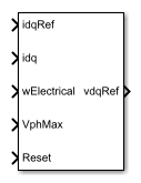
PMSM Current Controller with Pre-Control
Discrete-time permanent magnet synchronous machine current controller with pre-control
Libraries:
Simscape /
Electrical /
Control /
PMSM Control
Description
The PMSM Current Controller with Pre-Control block implements a discrete-time PI-based permanent magnet synchronous machine (PMSM) current controller in the rotor d-q reference frame with internal feedforward pre-control.
You typically use this block in a series of blocks making up a control structure.
You can generate a current reference in the d-q frame to be used as an input to this block with a PMSM Current Reference Generator.
You can obtain a voltage reference in the abc domain by converting the output of this block using an Inverse Park Transform block.
You can see an example of a full control structure, from machine measurements to machine inputs, in the PMSM Field-Oriented Control block.
Equations
The block is discretized using the backward Euler method due to its first-order simplicity and its stability.
Two PI current controllers implemented in the rotor reference frame produce the reference voltage vector:
and
where:
and are the d-axis and q-axis reference voltages, respectively.
and are the d-axis and q-axis reference currents, respectively.
and are the d-axis and q-axis currents, respectively.
Kp_id and Kp_iq are the proportional gains for the d-axis and q-axis controllers, respectively.
Ki_id and Ki_iq are the integral gains for the d-axis and q-axis controllers, respectively.
Ts is the sample time of the discrete controller.
vd_FF and vq_FF are the feedforward voltages for the d-axis and q-axis, respectively.
The feedforward voltages are obtained from the machine mathematical equations:
and
where:
ωe is the rotor electrical velocity.
Ld and Lq are the d-axis and q-axis inductances, respectively.
ψm is the permanent magnet flux linkage.
Zero Cancellation
Using PI control results in a zero in the closed-loop transfer function, which can result in undesired overshoot in the closed-loop response. This zero can be canceled by introducing a zero-cancelation block in the feedforward path. The zero cancellation transfer functions in discrete time are:
and
Voltage Saturation
Saturation must be imposed when the stator voltage vector exceeds the voltage phase limit Vph_max:
where vd and vq are the d-axis and q-axis voltages, respectively.
In the case of axis prioritization, the voltages v1 and v2 are introduced, where:
v1 = vd and v2 = vq for d-axis prioritization.
v1 = vq and v2 = vd for q-axis prioritization.
The constrained (saturated) voltages and are obtained as follows:
and
where:
and are the unconstrained (unsaturated) voltages.
v2_max is the maximum value of v2 that does not exceed the voltage phase limit, given by
In the case that the direct and quadrature axes have the same priority (d-q equivalence), the constrained voltages are obtained as follows:
and
where:
and
Integral Anti-Windup
An anti-windup mechanism is employed to avoid saturation of integrator output. In such a situation, the integrator gains become:
and
where Kaw_id, Kaw_iq, and Kaw_if are the anti-windup gains for the d-axis, q-axis, and field controllers, respectively.
Assumptions
The plant model for direct and quadrature axis can be approximated with a first-order system.
This control solution is used only for permanent magnet synchronous motors with sinusoidal flux distribution and field windings.
Examples

Electric Engine Dyno
Model an electric vehicle dynamometer test. The test environment contains an asynchronous machine (ASM) and an interior permanent magnet synchronous machine (IPMSM) connected back-to-back through a mechanical shaft. Both machines are fed by high-voltage batteries through controlled three-phase converters. The 164 kW ASM produces the load torque. The 35 kW IPMSM is the electric machine under test. The Control Machine Under Test (IPMSM) subsystem controls the torque of the IPMSM. The controller includes a multi-rate PI-based control structure. The rate of the open-loop torque control is slower than the rate of the closed-loop current control. The task scheduling for the controller is implemented as a Stateflow® state machine. The Control Load Machine (ASM) subsystem uses a single rate to control the speed of the ASM. The Visualization subsystem contains scopes that allow you to see the simulation results.

Energy Balance in a 48V Starter Generator
An interior permanent magnet synchronous machine (IPMSM) used as a starter/generator in a simplified 48V automotive system. The system contains a 48V electric network and a 12V electric network. The internal combustion engine (ICE) is represented by basic mechanical blocks. The IPMSM operates as a motor until the ICE reaches the idle speed and then it operates as a generator. The IPMSM supplies power to the 48V network, which contains the R3 power consumer. The 48V network supplies power to the 12V network which has two consumers: R1 and R2. The total simulation time (t) is 0.5 seconds. At t = 0.05 seconds, the ICE turns on. At t = 0.1 seconds, R3 switches on. At t = 0.3 seconds, R2 switches on and increases the load on the 12V electric network. The EM Controller subsystem includes a multi-rate PI-based cascade control structure which has an outer voltage-control loop and two inner current-control loops. The task scheduling in the Control subsystem is implemented as a Stateflow® state machine. The DCDC Controller subsystem implements a simple PI controller for the DC-DC Buck converter, which feeds the 12V network. The Scopes subsystem contains scopes that allow you to see the simulation results.

IPMSG Voltage Stabilization
Control an Interior Permanent Magnet Synchronous Generator (IPMSG) based low voltage generator system for a hybrid electric vehicle (HEV). The Control subsystem includes a multi-rate PI-based cascade control structure which has an outer voltage-control loop and two inner current-control loops. The task scheduling in the Control subsystem is implemented as a Stateflow® state machine. The Scopes subsystem contains scopes that allow you to see the simulation results. An ideal angular velocity source, which represents a combustion engine, drives the IPMSG. The IPMSG supplies low-voltage power to loads R1 and R2. At t = 0.4 seconds, the switch closes, increasing the load.

IPMSM Torque Control in a Parallel HEV
A simplified parallel hybrid electric vehicle (HEV). An interior permanent magnet synchronous machine (IPMSM) and an internal combustion engine (ICE) provide the vehicle propulsion. The IPMSM operates in both motoring and generating modes. The vehicle transmission and differential are implemented using a fixed-ratio gear-reduction model. The Vehicle Controller subsystem converts the driver inputs into torque commands. The vehicle control strategy is implemented as a Stateflow® state machine. The ICE Controller subsystem controls the torque of the combustion engine. The Drive Controller subsystem controls the torque of the IPMSM. The Scopes subsystem contains scopes that allow you to see the simulation results.

IPMSM Torque Control in a Series HEV
An interior permanent magnet synchronous machine (IPMSM) propelling a simplified series hybrid electric vehicle (HEV). An ideal DCDC converter, connected to a high-voltage battery, feeds the IPMSM through a controlled three-phase converter. A combustion engine driven generator charges the high-voltage battery. The vehicle transmission and differential are implemented using a fixed-ratio gear-reduction model. The Vehicle Controller subsystem converts the driver inputs into relevant commands for the IPMSM and generator. The Drive Controller subsystem controls the torque of the IPMSM. The controller includes a multi-rate PI-based control structure. The rate of the open-loop torque control is slower than the rate of the closed-loop current control. The task scheduling for the controller is implemented as a Stateflow® state machine. The Scopes subsystem contains scopes that allow you to see the simulation results.

IPMSM Torque Control in a Series-Parallel HEV
A simplified series-parallel hybrid electric vehicle (HEV). An interior permanent magnet synchronous machine (IPMSM) and an internal combustion engine (ICE) provide the vehicle propulsion. The ICE also uses electric generator to recharge the high-voltage battery during driving. The vehicle transmission and differential are implemented using a fixed-ratio gear-reduction model. The Vehicle Controller subsystem converts the driver inputs into torque commands. The vehicle control strategy is implemented as a Stateflow® state machine. The ICE Controller subsystem controls the torque of the combustion engine. The Generator Controller subsystem controls the torque of the electric generator. The Drive Controller subsystem controls the torque of the IPMSM. The Scopes subsystem contains scopes that allow you to see the simulation results.

IPMSM Torque Control in an Axle-Drive HEV
An interior permanent magnet synchronous machine (IPMSM) propelling a simplified axle-drive electric vehicle. A high-voltage battery feeds the IPMSM through a controlled three-phase converter. The IPMSM operates in both motoring and generating modes. The vehicle transmission and differential are implemented using a fixed-ratio gear reduction model. The Vehicle Controller subsystem converts the driver inputs into a relevant torque command. The Drive Controller subsystem controls the torque of the IPMSM. The controller includes a multi-rate PI-based control structure. The rate of the open-loop torque control is slower than the rate of the closed-loop current control. The task scheduling for the controller is implemented as a Stateflow® state machine. The Scopes subsystem contains scopes that allow you to see the simulation results.

IPMSM Velocity Control
Control the rotor angular velocity in an interior permanent magnet synchronous machine (IPMSM) based automotive electrical-traction drive. A high-voltage battery feeds the IPMSM through a controlled three-phase converter. The IPMSM operates in both motoring and generating modes according to the load. An ideal torque source provides the load. The Scopes subsystem contains scopes that allow you to see the simulation results. The Control subsystem includes a multi-rate PI-based cascade control structure which has an outer angular-velocity-control loop and two inner current-control loops. The task scheduling in the Control subsystem is implemented as a Stateflow® state machine. During the one-second simulation, the angular velocity demand is 0 rpm, 500 rpm, 2000 rpm, and then 3000 rpm.
Ports
Input
Output
Parameters
References
[1] Bernardes, T., V. F. Montagner, H. A. Gründling, and H. Pinheiro. "Discrete-time sliding mode observer for sensorless vector control of permanent magnet synchronous machine." IEEE Transactions on Industrial Electronics. Vol. 61, Number 4, 2014, pp. 1679–1691.
[2] Carpiuc, S., and C. Lazar. "Fast real-time constrained predictive current control in permanent magnet synchronous machine-based automotive traction drives." IEEE Transactions on Transportation Electrification. Vol.1, Number 4, 2015, pp. 326–335.
Extended Capabilities
Version History
Introduced in R2017b