NPN Bipolar Transistor Characteristics
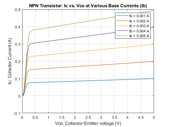
This example shows generation of the Ic versus Vce curve for an NPN bipolar transistor. Define the vector of base currents and minimum and maximum collector-emitter voltages by double clicking on the block labeled 'Define Conditions (Ib and Vce)'. Run the tests and generate plots of the curves by clicking in the model on hyperlink 'plot curves'.
This type of plot can be compared against a manufacturer datasheet to confirm a correct implementation of the transistor parameters. You can also use this model to examine the transistor characteristics in the reverse region by specifying a range of negative Vce values. In this region, the gain is defined by the Reverse current transfer ratio BR parameter. Increase this parameter above one to produce a reverse current gain.
To explore the properties of a PNP bipolar transistor, open model PNPCharacteristics.
Model

Simulation Results from Simscape Logging
The plot below shows collector current (Ic) versus collector-emitter voltage (Vce) characteristics for different levels of base current (Ib).
