Configuring Acquisition Window Width for ADC Blocks
What Is an Acquisition Window?
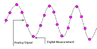
ADC blocks take a signal from an analog source and measure it with a digital device. The digital device does not measure in a continuous process, but in a series of discrete measurements, close enough together to approximate the source signal with the required accuracy.
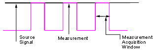
The digital measurement itself is not an instantaneous process, but is a measurement window, where the signal is acquired and measured, as shown in the following figure.
Ideally, when the measurement window is opened, the actual signal coming in would be measured perfectly. In reality the signal does not reach its full magnitude immediately. The measurement process can be modeled by a circuit similar to the one shown in the following figure for the ADC found on the F2812 eZdsp,
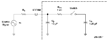
where the measurement circuit is characterized by a certain capacitance. In the preceding figure, when the switch is closed, the measurement begins. In this circuit, which is characterized by its capacitance, the signal received is not in a form of a step function as shown by the ideal measurement, but a ramp up to the true signal magnitude. The following figure shows what happens to the signal when the sampler switch is closed and the signal is received to be measured.
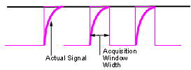
Because the signal acquisition is not instantaneous, it is very important to set a wide enough acquisition window to allow the signal to ramp up to full strength before the measurement is taken. If the window is too narrow, the measurement is taken before the signal has reached its full magnitude, resulting in erroneous data. If the window is too wide, the source signal itself may change, and the sampling may be too infrequent to reflect the actual value, also resulting in erroneous data. You must calculate the width of the acquisition window based on the circuit characteristics of resistance and capacitance of your specific circuit. Then, using the ADC parameters described in the following section, you can configure the acquisition window width.
Configuring ADC Parameters for Acquisition Window Width
Accessing the ADC Parameters
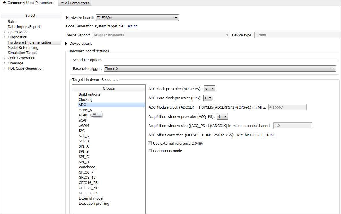
The ADC parameters can be set from the Peripherals tab of the Target hardware resources tab.
You can set ACQ_PS — Acquisition Prescaler — to a value from 0 to 15. To obtain the actual value, increment the setting by 1. This increment produces an actual range from 1 to 16.
You can set ADCLKPS — AD Clock Prescaler — to a value from 0 to 15. To obtain the actual value, increment the setting by 1. This increment produces an actual range from 1 to 16.
You can set CPS — Clock Prescaler — to a value from 0 to 1. To obtain the actual value, increment the setting by 1. This increment produces an actual range from 1 to 2.
These three prescalers serve to reduce the speed of the clock and to set the acquisition window width. The following diagram shows how these prescalers are used.
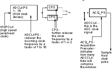
In the preceding diagram, the high-speed peripheral clock frequency is received and then divided by the ADCLKPS. The reduced clock frequency is then further divided by CPS. The resulting frequency is the ADCCLK signal. The value of ACQ_PS then determines how many ADCCLK ticks comprise one S/H (sample and hold) period, or in other words, the length of the acquisition window.
Configure Acquisition Window Width Using ADC Parameters
The following examples show how you can use ADC parameters to configure the acquisition window width:
Example 1:
If the HISPCLK = 30 MHz, and ADCLKPS=1 (which is a value of 2), the result is 15 MHz.
If CPS= 1 (which is a value of 2), then ADCCLK = 7.5 MHz.
If ACQ_PS = 0 (which is a value of 1), then the sample/hold period is 1 ADCCLK tick, or .1333 microseconds.
Example 2:
If the HISPCLK = 30 MHz, and ADCLKPS=1 (which is a value of 2), the result is 15 MHz.
If CPS= 1 (which is a value of 2), then ADCCLK = 7.5 MHz.
If ACQ_PS = 15 (which is a value of 16), then the sample/hold period is 16 ADCCLK ticks, or 2.1333 microseconds.
Note
HISPCLK is set automatically for the user, and it is not possible to change the rate. For more information, see High-Speed Peripheral Clock