Configure a Driving Simulator for Your Desktop with Virtual Vehicle Composer
You can configure a driving simulator for your desktop with the Virtual Vehicle Composer. This example shows how to run a driver-in-the-loop simulation using the Logitech® G29 steering wheel and pedals.
Connect Game Wheel Hardware
Connect the Logitech G29 steering wheel and pedals hardware to the USB port on the target computer.
Tip
You must have Logitech G Hub installed and running prior to executing this workflow. For more information, see Logitech G Hub.
Build Virtual Vehicle Model
Build a virtual vehicle model with combined longitudinal and lateral dynamics.
Navigate to the MATLAB® toolstrip. On the Apps tab, click the down arrow on the far right of the toolstrip to expand the apps gallery, and then select Virtual Vehicle Composer.
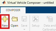
To create a new virtual vehicle model, on the Virtual Vehicle Composer toolstrip, on the Composer tab, click New.
On the Setup tab in the Virtual Vehicle Composer, configure these settings for a passenger vehicle:
Powertrain architecture —
Conventional VehicleYou can also select an electric vehicle or hybrid vehicle. For more information, see Powertrain architecture (Powertrain Blockset).
Vehicle dynamics —
Combined
                                        Longitudinal and Lateral Dynamics
Model template —
Simulink
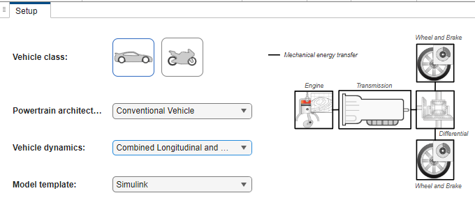
Click Confirm Setup.
Click Build Virtual Vehicle.
Configure Game Wheel Hardware
Configure the game wheel hardware using the Driver Commands block.
In the Driver Commands block, from the Vehicle command mode list, select
Game Wheel
                            Hardware
.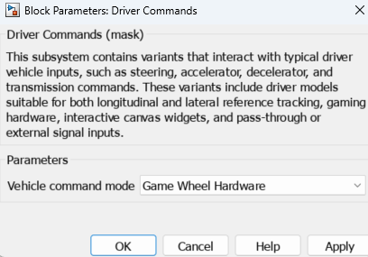
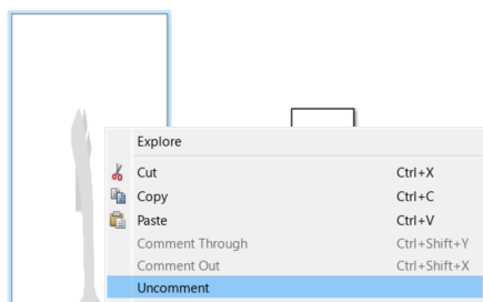
Right-click the Driver Commands block and select Mask > Look Under Mask.
In the
Driver Commands/Driver Commands/Game Wheel
                            Hardware
subsystem, right-click the Simulation 3D Joystick block and select Uncomment to enable the block.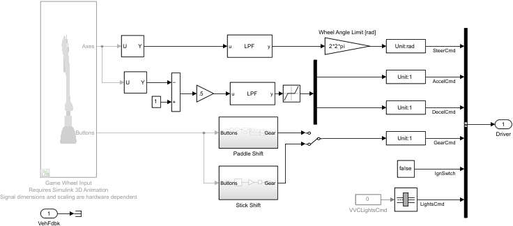
3D Environment Setup
Configure the 3D environment to use the ZalaZONE Automotive Proving Ground High-Speed Handling Course scene with the recommended starting location and enable the 3D engine.
3D Scene Setup
In the
Environmentsubsystem, right-click theGround Feedbacksubsystem and select Variant > Label Mode Active Choice > 1 (3D Engine).In the
Visualizationsubsystem, right-click the3D Enginesubsystem and select Variant > Label Mode Active Choice > Engine3D (3D Engine).In the
Visualization>3D Enginesubsystem, open the Simulation 3D Scene Configuration block.
For this example, for the Simulation 3D Scene Configuration block:
Set Scene name to
ZalaZONE High-speed Handling Course.Set Scene view to
SimulinkVehicle1.
Note
If the scene is not available in the Scene name parameter drop-down list, you must install it. See Setup.
Click OK and save the model.
Starting Location Setup
Open the Model Explorer.
In the Model Hierarchy pane, navigate to ConfiguredVirtualVehicleModel > External Data > VirtualVehicleTemplate.
In the list of Referenced Dictionaries, select
PassVeh. Click Open.
In the Model Hierarchy pane, select ConfiguredVirtualVehicleModel > PassVeh > Design Data.
Set the data dictionary variable value to the initial vehicle position values recommended for the scene. For this example, use these recommended values for the ZalaZONE Automotive Proving Ground High-Speed Handling Course scene.
Data Dictionary Variable Description Recommended Value PlntVehInitLongPosRecommended starting location - X
1182PlntVehInitLatPosRecommended starting location - Y
-347PlntVehInitVertPosRecommended starting location - Z
-230.5PlntVehInitRollAngRecommended starting location - Roll
0PlntVehInitPitchAngRecommended starting location - Pitch
0PlntVehInitYawAngRecommended starting location - Yaw
28.6In the
PassVehdata dictionary, confirm the variable values match the recommended starting values for the scene.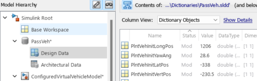
In the Model Explorer, save the
PassVehchanges.
Run Simulation
Optionally, to run the simulation in soft real-time, enable simulation pacing by clicking the down arrow on the Run button, and then select Simulation Pacing.
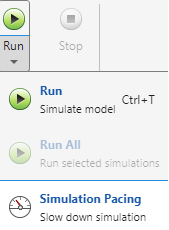
From the Simulation Pacing Options: ConfiguredVirtualVehicleModel dialog box, select Enable pacing to slow down simulation.
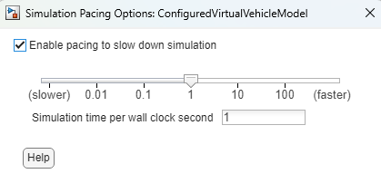
On the
ConfiguredVirtualVehicleModelmodel toolstrip, click Run.Drive the vehicle around the track using the steering wheel and pedals. As the simulation runs, view the results in the Simulation 3D Viewer.
See Also
Virtual Vehicle Composer | ZalaZONE Automotive Proving Ground High-Speed Handling Course