Import and Simulate High-Fidelity Tire Models in Virtual Vehicle Models
For accuracy in simulating high-frequency driving events, use a high-fidelity tire model such as the Flexible Ring Tire (FTire) model by Cosin Scientific Software. You can import an FTire model into Virtual Vehicle Composer models for applications requiring multiple points of tire contact, such as modeling driving on inclement road surfaces, low-speed maneuvers, detailed braking development, NVH and harmonic analysis, and tire wear. This example shows how to import an FTire model into a Virtual Vehicle Composer model using custom components and simulates a double-lane change maneuver.

Tip
You must have FTire/core and FTire/link installed prior to executing this workflow. For more information, see Cosin Scientific Software.
Build Virtual Vehicle with FTire Components
Import FTire custom components and build a virtual vehicle model.
Navigate to the MATLAB® toolstrip. On the Apps tab, click the down arrow on the far right of the toolstrip to expand the apps gallery, and then select Virtual Vehicle Composer.
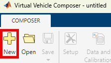
To create a new virtual vehicle model, on the Virtual Vehicle Composer toolstrip, on the Composer tab, click New.
On the Setup tab in the Virtual Vehicle Composer app, configure these settings for a passenger vehicle:
Powertrain architecture —
Conventional VehicleYou can also select an electric vehicle or hybrid vehicle. For more information, see Powertrain architecture.
Vehicle dynamics —
Combined
                                    Longitudinal and Lateral Dynamics
Model template —
Simulink
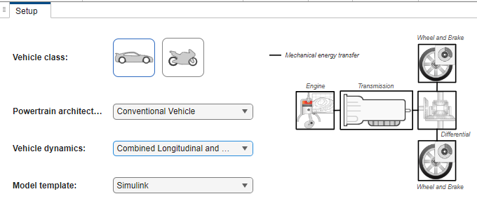
Click Confirm Setup.
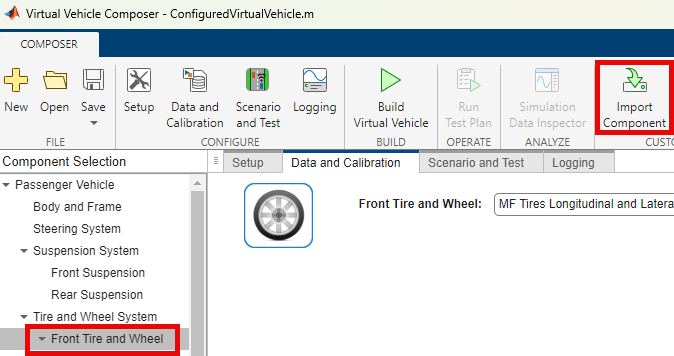
Click the Data and Calibration tab.
From the Component Selection tree, select Front Tire and Wheel. On the toolstrip, click Import Component.
The Import Component dialog box opens. To import the
FTireTiresFront.slxcomponent model, click Browse. You can find this file by navigating toMATLAB\Projects\examples\VirtualVehicle\PassVeh\Plant.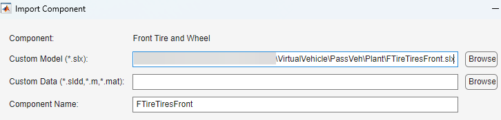
For more information importing custom components, see Add Virtual Vehicle Custom Component.
Repeat steps 2 and 3 for the Rear Tire and Wheel component, importing the
FTireTiresRear.slxmodel.Note
When configuring a virtual vehicle model with a one-axle trailer, the FTire models do not apply to the wheels and tires of the trailer.
Navigate to the Scenario and Test pane and configure these settings:
Scenario —
Double Lane
                    Change
3D Scene Selection —
3D
                    Scene
Click Build Virtual Vehicle.
Enable FTire Variant Subsystem
After you build your virtual vehicle, enable the FTire subsystem
variant for the front and rear wheels. By default, a pictorial representation of the
FTire subsystem is selected as the active variant.
Navigate to the
Vehicle/ConfiguredSimulinkPlantModel (ConfiguredSimulinkPlantModel)/Front Wheels/FTireTiresFront (FTireTiresFront)subsystem.Right-click the
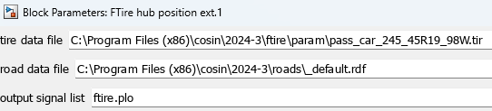
FTirevariant subsystem and set Active Variant toFTire hub position ext.
Update the FTire library block to use the road and tire files from your specific FTire installation.
Note
If you select a different tire size, you must update the Unloaded Radius Offset value, the vertical position of the wheel to a position above ground, and the chassis position. Otherwise, initialization errors can occur related to the initial position.
Repeat steps 1 and 2 for the
Vehicle/ConfiguredSimulinkPlantModel
                        (ConfiguredSimulinkPlantModel)/Rear Wheels/FTireTiresRear
                        (FTireTiresRear)/FTire
subsystem.
Run Co-Simulation with FTire
On the ConfiguredVirtualVehicleModel model toolstrip, click
Run. As the simulation runs, view the simulation results using
the Simulation 3D Viewer and the Cosin animation dialog box.
Note
The 3D scene does not use the FTire geometry. You must align the 3D scene with the FTire road model to keep them in sync. In this example the road file and the 3D scene are both flat and have the same ground.
For more information using FTire features in a Simulink® environment, see FTire/link.
See Also
Set Up Virtual Vehicle Architecture | Add Virtual Vehicle Custom Component