Modulate and Demodulate OFDM Streaming Samples
This example model shows how to use OFDM Modulator and OFDM Demodulator blocks in Wireless HDL Toolbox™. In this example, an OFDM Modulator and an OFDM Demodulator block are connected back-to-back. The OFDM parameters source parameter in these blocks is set to Input port, enabling you to dynamically change the input values of these blocks. You can change these values using the script in this example. These blocks support scalar and vector inputs. To verify the functionality of these blocks, the input provided to the OFDM Modulator block is compared with the output of the OFDM Demodulator block. The OFDMModDemod HDL subsystem in this example supports HDL code generation.
Set Up Input Parameters
Set up these workspace variables for the Simulink® model to use. You can modify these values according to your requirement. The model in this example uses these workspace variables fftLen, maxFFTLen, cpLen, numLG, numRG, numSymb, and DCNull to configure the OFDM Modulator and OFDM Demodulator blocks.
fftLen = 64;       % FFT length
maxFFTLen = 128;   % Maximum FFT length
cpLen = 16;        % Cylic prefix length
numLG = 6;         % Number of left guard carriers
numRG = 5;         % Number of right guard carriers
numSymb = 2;       % Number of right guard carriers
DCNull = 1;        % 1 or 0
vecLen = 4;        % Vector length - 1, 2, 4, 8, 16, 32, or 64
if DCNull==1
    numActData = fftLen - (numLG+numRG+1);
else
    numActData = fftLen - (numLG+numRG);
end
Generate Input Data Frames
Generate random frames of complex input data and a control signal that indicates the frame boundaries.
rng default;
dataIn = complex(randn(numActData*numSymb,1),randn(numActData*numSymb,1));
dataVec = []; % Store data arranged in vector form
presentSymbDataStartIndex = 0;
for ii = 1:numSymb
    counter = 0;
    for jj = 1:ceil(numActData/vecLen)
        if jj == ceil(numActData/vecLen)
            numZerosTobeAppended = vecLen - (numActData-counter);
            dataVec = [dataVec [dataIn(presentSymbDataStartIndex+counter+(1:vecLen-numZerosTobeAppended));zeros(1,numZerosTobeAppended).']];
        else
            dataVec = [dataVec dataIn(presentSymbDataStartIndex+counter+(1:vecLen))];
        end
        counter = counter + vecLen;
    end
    presentSymbDataStartIndex = presentSymbDataStartIndex + numActData;
end

data = dataVec.';
valid = boolean(ones(size(data,1),1)); % Valid signal generation

sampling_time = 1;
stoptime = maxFFTLen*6*numSymb;
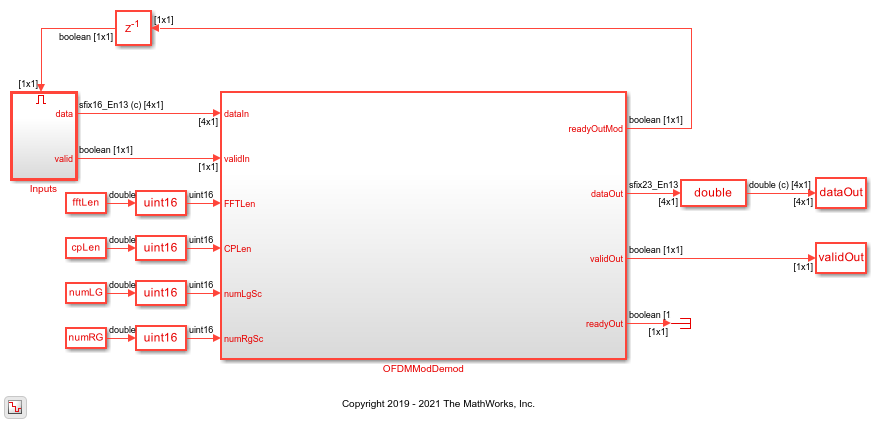
Run Simulink Model
Run the model to import the input signal variables dataIn, validIn, fftLen, maxFFTLen, cpLen, numLG, numRG, numSymb, and DCNull from the workspace to the OFDM Modulator block. The OFDM Modulator block returns OFDM-modulated output samples and a control signal. These OFDM-modulated samples are fed to the OFDM Demodulator block, which returns OFDM demodulated samples.
open_system('genhdlOFDMModDemodExample')
sim('genhdlOFDMModDemodExample');

% Store valid data from Simulink model
dataOut1 = dataOut.data;
simOut = dataOut1(:,:,validOut);
simOut = simOut(:);
Compare OFDM Modulator Input with OFDM Demodulator Output
Compare the input data provided to the OFDM Modulator block with the output data generated from the OFDM Demodulator block.
figure('units','normalized','outerposition',[0 0 1 1])
subplot(2,1,1);
plot(real(dataIn(1:size(simOut,1))));
hold on
plot(squeeze(real(simOut)));
legend('Real part of reference data','Real part of demodulated data');
title('Comparison of OFDM Modulator Input with OFDM Demodulator Output - Real Part');
xlabel('OFDM Subcarriers');
ylabel('Real Part');

subplot(2,1,2)
plot(imag(dataIn(1:size(simOut,1))));
hold on
plot(squeeze(imag(simOut)))
legend('Imaginary part of reference data','Imaginary part of demodulated data');
title('Comparison of OFDM Modulator Input with OFDM Demodulator Output - Imaginary Part');
xlabel('OFDM Subcarriers');
ylabel('Imaginary Part');
