Boost Drive Shaft
Boost drive shaft speed
Libraries:
Powertrain Blockset /
Propulsion /
Combustion Engine Components /
Boost
Description
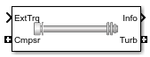
The Boost Drive Shaft block uses the compressor, turbine, and external torques to calculate the drive shaft speed. Use the block to model turbochargers and superchargers in an engine model.
You can specify these configurations:
Turbocharger — Connect the compressor to the turbine
Two-way ports for turbine and compressor connections
Option to add an externally applied input torque
Compressor only — Connect the drive shaft to the compressor
Two-way port for compressor connection
Externally applied input torque
Turbine only — Connect the drive shaft to the turbine
Two-way port for turbine connection
Externally applied load torque
For the Turbine only and Turbocharger configurations,
the block modifies the turbine torque with a mechanical efficiency.
Equations
The Boost Drive Shaft block applies Newton’s Second Law for Rotation. Positive torques cause the drive shaft to accelerate. Negative torques impose a load and decelerate the drive shaft.
The block also calculates the power loss due to mechanical inefficiency.
| Calculation | Equations |
|---|---|
| Shaft dynamics | with initial speed ω0 |
Speed constraint |
|
Power loss |
|
Power Accounting
For the power accounting, the block implements these equations.
| Bus Signal | Description | Equations | ||
|---|---|---|---|---|
|
| PwrCmpsr | Shaft power from compressor | |
| Shaft power from turbine | |||
PwrExt | Externally applied power | |||
|
| PwrMechLoss | Mechanical power loss | ||
|
| PwrStoredDriveshft | Rate change in rotational kinetic energy | ||
The equations use these variables.
| ω | Shaft speed |
| ω0 | Initial drive shaft speed |
| ωmin | Minimum drive shaft speed |
| ωmax | Maximum drive shaft speed |
| Jshaft | Shaft inertia |
| ηmax | Mechanical efficiency of turbine |
| τcomp | Compressor torque |
| τturb | Turbine torque |
| τext | Externally applied torque. |
Power loss due to mechanical inefficiency |
Examples

Build Conventional Vehicle Model
Build a vehicle with an internal combustion engine using the conventional vehicle reference application.
Ports
Input
Output
Parameters
Extended Capabilities
Version History
Introduced in R2017a