Configure AUTOSAR Mode-Switch Communication
AUTOSAR mode-switch (M-S) communication relies on a mode manager and connected mode users. The mode manager is an authoritative source for software components to query the current mode and to receive notification when the mode changes (switches). A mode manager can be provided by AUTOSAR Basic Software (BSW) or implemented as an AUTOSAR software component. A mode manager implemented as a software component is called an application mode manager. A software component that queries the mode manager and receives notifications of mode switches is a mode user.
Configure Mode Receiver Port and Mode-Switch Event for Mode User
To model a mode user software component, use an AUTOSAR mode receiver port and a mode-switch event. The mode receiver port uses a mode-switch (M-S) interface to connect and communicate with a mode manager, which provides notifications of mode changes. You configure a mode-switch event to respond to a specified mode change by activating an associated runnable. This example shows how to configure an AUTOSAR mode-receiver port, mode-switch event, and related elements for a mode user.
Note
This example does not implement a meaningful algorithm for controlling component execution based on the current ECU mode.
Open a writable copy of the example model
autosar_swc_expfcns.Declare a mode declaration group — a group of mode values — using Simulink® enumeration. Specify the storage type as an unsigned integer. Enter the following command in the MATLAB® Command Window:
Simulink.defineIntEnumType('mdgEcuModes', ...
 {'Run', 'Sleep'}, [0;1], ...
 'Description', 'Mode declaration group for ECU modes', ...
 'DefaultValue', 'Run', ...
 'HeaderFile', 'Rte_Type.h', ...
 'AddClassNameToEnumNames', false,...
 'StorageType', 'uint16');
Rename the Simulink inport
RPort_DE1 (ErrorStatus)toMRPort (ECU mode). For example, open the Model Data Editor (on the Modeling tab, click Model Data Editor). Use the Source column to rename the inport. In a later step, you will map this inport to an AUTOSAR mode-receiver port.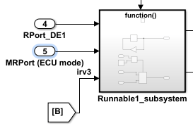
Next, apply the mode declaration group
mdgEcuModesto the inport. In the Model Data Editor, for the inport, set Data Type toEnum: mdgEcuModes. Additionally, set Complexity toauto.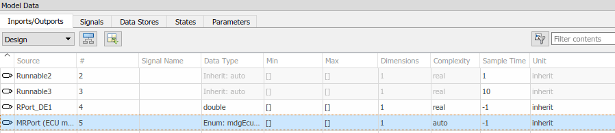
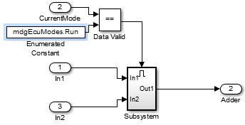
In the model window, open the function-call subsystem named
Runnable1_subsystemand make the following changes:Rename inport
ErrorStatustoCurrentMode.Replace Constant block
RTE_E_OKwith an Enumerated Constant block. (The Enumerated Constant block can be found in the Sources block group.) Double-click the block to open its block parameters dialog box. Set Output data type toEnum: mdgEcuModesand set Value tomdgEcuModes.Run. Click OK.
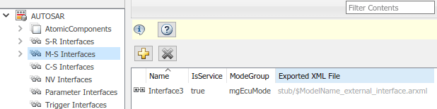
Add an AUTOSAR mode-switch interface to the model. Open the AUTOSAR Dictionary. Select M-S Interfaces. Click the Add button
 . In the Add Interfaces dialog box,
specify Name as
. In the Add Interfaces dialog box,
specify Name as Interface3and specify ModeGroup asmgEcuMode.The IsService property of an M-S interface defaults to
true. For the purposes of this example, you can leave IsService at its default setting, unless you have a reason to change it.Click Add.
The value you specify for the AUTOSAR mode group is used in a later step, when you map a Simulink inport to an AUTOSAR mode-receiver port and element.
Add an AUTOSAR mode-receiver port to the model. Expand AtomicComponents, expand component
ASWC, and select ModeReceiverPorts. To open the Add Ports dialog box, click the Add button. In the Add Ports dialog box, specify
Name as MRPort. Interface is already set toInterface3(the only available value in this configuration), and Type is already set toModeReceiver. Click Add.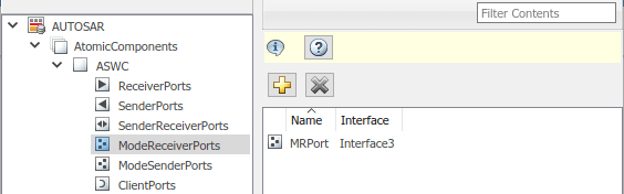
In the Code Mappings editor, map the Simulink inport
MRPort (ECU mode)to the AUTOSAR mode-receiver port and element. Open the Code Mappings editor and select the Inports tab. In the row for inportMRPort (ECU mode), set DataAccessMode toModeReceive, set Port toMRPort, and set Element tomgEcuMode. (The AUTOSAR element value matches the ModeGroup value you specified when you added AUTOSAR mode-switch interfaceInterface3.)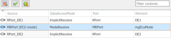
This step completes the AUTOSAR mode-receiver port configuration. Click the Validate button
 to validate the AUTOSAR component
configuration. If errors are reported, address them and then retry
validation. When the model passes validation, save the model.
to validate the AUTOSAR component
configuration. If errors are reported, address them and then retry
validation. When the model passes validation, save the model.Note
The remaining steps create an AUTOSAR mode-switch event and set it up to trigger activation of an AUTOSAR runnable. If you intend to use ECU modes to control program execution, without using an event to activate a runnable, you can skip the remaining steps and implement the required flow-control logic in your design.
To add an AUTOSAR mode-switch event for a runnable:
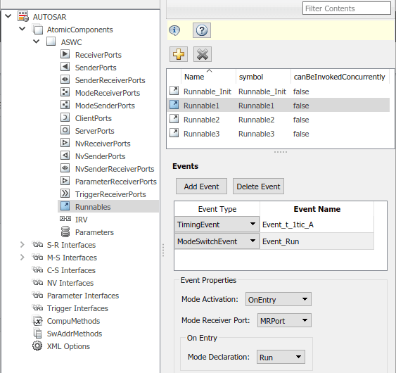
Open the AUTOSAR Dictionary. Expand AtomicComponents, expand the
ASWCcomponent, and select Runnables. In the list of runnables, selectRunnable1. This selection activates an Events configuration pane for the runnable.To add an event to the list of events for
Runnable1, click Add Event. For the new event, set Event Type toModeSwitchEvent. (This activates an Event Properties subpane.) Specify Event Name asEvent_Run.In the Event Properties subpane, set Mode Activation to
OnEntry, set Mode Receiver Port toMRPort, and set Mode Declaration toRun. Click Apply.
Open the Code Mappings editor and select the Functions tab. In this example model, Simulink entry-point functions have already been mapped to AUTOSAR runnables, including the runnable
Runnable1, to which you just added a mode-switch event.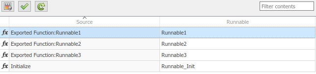
This completes the AUTOSAR mode-switch event configuration. Click the Validate button
to validate the AUTOSAR component
configuration. If errors are reported, address them and then retry
validation. When the model passes validation, save the model. Optionally,
you can generate XML and C code from the model and inspect the
results.
Configure Mode Sender Port and Mode Switch Point for Application Mode Manager
To model an application mode manager software component, use an AUTOSAR mode sender port. Mode sender ports use a mode-switch (M-S) interface to output a mode switch to connected mode user components.
You model the mode sender port as a model root outport, which is mapped to an AUTOSAR mode sender port and a mode-switch (M-S) interface. The outport data type is an enumeration class with an unsigned integer storage type, representing an AUTOSAR mode declaration group.
This example shows how to configure a mode sender port and related elements for an application mode manager.
Open a model configured for AUTOSAR code generation. This example uses a model that contains Stateflow® logic for maintaining engine state. The model outputs the current engine mode value.
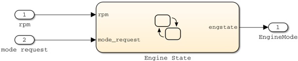
Declare a mode declaration group — a group of mode values. You can declare mode values with Simulink enumeration. In this example, the Stateflow logic defines
EngineModesvaluesOff,Crank,Stall,Idle, andRun. For example: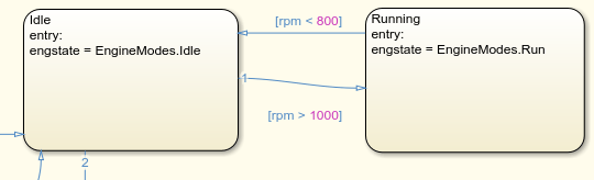
Add an AUTOSAR M-S interface to the model. Open the AUTOSAR Dictionary and select M-S Interfaces. Click the Add button
. In the Add Interfaces dialog box, set
IsService to trueand enter a ModeGroup name. In this example, the mode declaration group isEngineModes.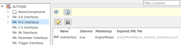
Add an AUTOSAR mode sender port to the model. Expand AtomicComponents, expand the component, and select ModeSenderPorts. Click the Add button
. In the Add Ports dialog box, set
Interface to the name of the M-S interface you
created.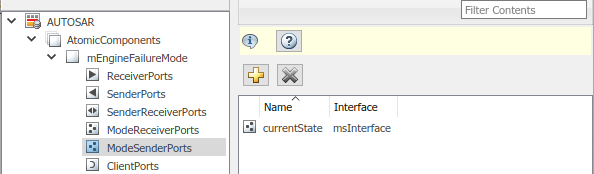
Map the Simulink outport that outputs the mode value to the AUTOSAR mode sender port you created. Open the Code Mappings editor and select the Outports tab. To map the outport to the AUTOSAR mode sender port, set DataAccessMode to
ModeSend, select the Port name, and for Element, select the mode declaration group name that you specified for the M-S interface.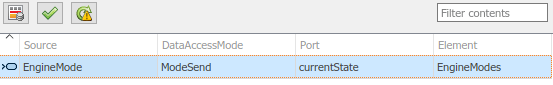
Generate code for the model.
The ARXML code includes referenced ModeSwitchPoints, ModeSwitchInterfaces, and ModeDeclarationGroups. For example, the following ARXML code describes the ModeSwitchPoint for the AUTOSAR mode sender port.
<RUNNABLE-ENTITY>
  ...
  <MODE-SWITCH-POINTS>
    <MODE-SWITCH-POINT UUID="...">
      <SHORT-NAME>OUT_currentState_EngineModes</SHORT-NAME>
      <MODE-GROUP-IREF>
        <CONTEXT-P-PORT-REF DEST="P-PORT-PROTOTYPE">/pkg/swc/mEngineFailureMode/currentState
          </CONTEXT-P-PORT-REF>
        <TARGET-MODE-GROUP-REF DEST="MODE-DECLARATION-GROUP-PROTOTYPE">
          /pkg/if/msInterface/EngineModes</TARGET-MODE-GROUP-REF>
      </MODE-GROUP-IREF>
    </MODE-SWITCH-POINT>
  </MODE-SWITCH-POINTS>
  ...
</RUNNABLE-ENTITY>
The C code includes
Rte_SwitchAPI calls to communicate mode switches to other software components. For example, the following code communicates anEngineModesmode switch./* Outport: '<Root>/EngineMode' */ Rte_Switch_currentState_EngineModes(mEngineFailureMode_B.engstate);