Model AUTOSAR Communication
In Simulink®, for the Classic Platform, you can model AUTOSAR sender-receiver (S-R), client-server (C-S), mode-switch (M-S), nonvolatile (NV) data, parameter, and trigger communication.
About AUTOSAR Communication
AUTOSAR software components provide well-defined connection points called ports. There are three types of AUTOSAR ports:
Require(In)Provide(Out)Combined
Provide-Require(InOut — introduced in AUTOSAR schema version 4.1)
AUTOSAR ports can reference the following kinds of interfaces:
Sender-Receiver
Client-Server
Mode-Switch
Nonvolatile Data
Parameter
Trigger
The following figure shows an AUTOSAR software component with four ports representing the port and interface combinations for Sender-Receiver and Client-Server interfaces.

A Require port that references a Mode-Switch interface is called a
mode-receiver port.
Sender-Receiver Interface
In AUTOSAR port-based sender-receiver (S-R) communication, AUTOSAR software components read and write data to other components or services. To implement S-R communication, AUTOSAR software components define:
An AUTOSAR sender-receiver interface with data elements.
AUTOSAR provide and require ports that send and receive data.
In Simulink, you can:
Create AUTOSAR S-R interfaces and ports by using the AUTOSAR Dictionary.
Model AUTOSAR provide and require ports by using Simulink root-level outports and inports.
Map the outports and inports to AUTOSAR provide and require ports by using the Code Mappings editor.
A Sender-Receiver Interface consists of one or more data elements. Although a
Require, Provide, or
Provide-Require port can reference a Sender-Receiver Interface, the
AUTOSAR software component does not necessarily access all of
the data elements. For example, consider the following figure.

The AUTOSAR software component has a Require and
Provide port that references the same Sender-Receiver Interface,
Interface1. Although this interface contains data elements
DE1, DE2, DE3,
DE4, and DE5, the component does not utilize
all of the data elements.
The following figure is an example of how you model, in Simulink, an AUTOSAR software component that accesses data elements.
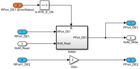
ASWC accesses data elements DE1 and
DE2. You model data element access as follows:
For
Requireports, use Simulink inports. For example,RPort_DE1andRPort1_DE2.For
Provideports, use Simulink outports. For example,PPort_DE1andPPort_DE2.For
Provide-Requireports (schema 4.1 or higher), use a Simulink inport and outport pair with matching data type, dimension, and signal type. For more information, see Configure AUTOSAR Provide-Require Port.
ErrorStatus is a value that the AUTOSAR Runtime Environment (RTE) returns to indicate errors that the communication system detects for each data element. Upon import from ARXML files ErrorStatus ports are added to receiver components if the associated sender-receiver data element meets at least one of these conditions:
The
INVALIDATION-POLICYset toKEEPorREPLACE.The
COM-SPECSof the element uses a positiveALIVE-TIMEOUTvalue.The
COM-SPECSof the element hasHANDLE-NEVER-RECEIVEDset totrue.The
COM-SPECSof the element hasUSES-END-TO-END-PROTECTIONset totrue.
You can use a Simulink inport to model error status, for example, RPort_DE1
(ErrorStatus).
Use the AUTOSAR Dictionary and the Code Mappings editor to specify the AUTOSAR settings for each inport and outport. For more information, see Configure AUTOSAR Sender-Receiver Communication.
Queued Sender-Receiver Interface
In AUTOSAR queued sender-receiver (S-R) communication, AUTOSAR software components read and write data to other components or services. Data sent by an AUTOSAR sender software component is added to a queue provided by the AUTOSAR Runtime Environment (RTE). Newly received data does not overwrite existing unread data. Later, a receiver software component reads the data from the queue.
To implement queued S-R communication, AUTOSAR software components define:
An AUTOSAR sender-receiver interface with data elements.
AUTOSAR provide and require ports that send and receive queued data.
In Simulink, you can:
Create AUTOSAR queued S-R interfaces and ports by using the AUTOSAR Dictionary.
Model AUTOSAR provide and require ports by using Simulink root-level outports and inports.
Map the outports and inports to AUTOSAR provide and require ports by using the Code Mappings editor. Set the AUTOSAR data access modes to
QueuedExplicitSendorQueuedExplicitReceive.
To model sending and receiving AUTOSAR data using a queue, use Simulink Send and Receive blocks. If your queued S-R communication implementation involves states or requires decision logic, use Stateflow® charts. You can handle errors that occur when the queue is empty or full. You can specify the size of the queue. For more information, see Simulink Messages Overview.
You can simulate AUTOSAR queued sender-receiver (S-R) communication between component models, for example, in a composition-level simulation. Data senders and receivers can run at different rates. Multiple data senders can communicate with a single data receiver.

To get started, you can import components with queued S-R interfaces and ports from ARXML files into Simulink, or use Simulink to create the interfaces and ports. For more information, see Configure AUTOSAR Queued Sender-Receiver Communication.
Client-Server Interface
AUTOSAR allows client-server communication between:
Application software components
An application software component and Basic Software
An AUTOSAR Client-Server Interface defines the interaction between a software component that provides the interface and a software component that requires the interface. The component that provides the interface is the server. The component that requires the interface is the client.
To model AUTOSAR clients and servers in Simulink, for simulation and code generation:
To model AUTOSAR servers, use Simulink Function blocks at the root level of a model.
To model AUTOSAR client invocations, use Function Caller blocks.
Use the function-call-based modeling style to create interconnected Simulink functions, function-calls, and root model inports and outports at the top level of a model.
This diagram illustrates a function-call framework in which Simulink Function blocks model AUTOSAR server runnables, Function Caller blocks model AUTOSAR client invocations, and Simulink data transfer lines model AUTOSAR inter-runnable variables (IRVs).

The high-level workflow for developing AUTOSAR clients and servers in Simulink is:
Model server functions and caller blocks in Simulink. For example, create Simulink Function blocks at the root level of a model, with corresponding Function Caller blocks that call the functions.
In the context of a model configured for AUTOSAR, map and configure the Simulink functions to AUTOSAR server runnables. Validate the configuration, simulate, and generate C code and ARXML files from the model.
In the context of another model configured for AUTOSAR, map and configure function caller blocks to AUTOSAR client ports and AUTOSAR operations. Validate the configuration, simulate, and generate C code and ARXML files from the model.
Integrate the generated C code into a test framework for testing, for example, with SIL simulation. (Ultimately, the generated C code and ARXML files are integrated into the AUTOSAR Runtime Environment (RTE).)
For more information, see AUTOSAR Client-Server Communication.
Mode-Switch Interface
AUTOSAR mode-switch (M-S) communication relies on a mode manager and connected mode users. The mode manager is an authoritative source for software components to query the current mode and to receive notification when the mode changes. A mode manager can be provided by AUTOSAR Basic Software (BSW) or implemented as an AUTOSAR software component. A mode manager implemented as a software component is called an application mode manager. A software component that queries the mode manager and receives notifications of mode changes is a mode user.
Mode User
To model an AUTOSAR mode user software component in Simulink:
Create an AUTOSAR mode-switch interface.
Create an AUTOSAR mode receiver port and map it to a Simulink inport.
For an initialization or other AUTOSAR runnable in the model, specify a mode-switch event to trigger the runnable.
To model an AUTOSAR software component mode-receiver port, general steps can include:
Declare a mode declaration group — a group of mode values — using Simulink enumeration. For example, you could create an enumerated type
mdgModes, with enumerated valuesMANUAL_ADJUSTandAUTO_ADJUST. Specify the storage type as an unsigned integer.Simulink.defineIntEnumType("mdgModes", ... {"MANUAL_ADJUST", "AUTO_ADJUST"}, ... [18 28], ... "Description", "Type definition of mdgModes.", ... "HeaderFile", "Rte_Type.h", ... "DefaultValue", "MANUAL_ADJUST", ... "AddClassNameToEnumNames", false,... "StorageType", "uint16"... );
Apply the enumeration data type to a Simulink inport that represents an AUTOSAR mode-receiver port. In this Inport block dialog box, enumerated type
mdgModesis specified as the inport data type.
To specify the mapping of the Simulink inport to the AUTOSAR mode-receiver port, use the Code Mappings editor (or equivalent AUTOSAR map functions).
In the following example, in the Inports tab of the Code Mappings editor, Simulink inport
mode_receiveis mapped to AUTOSAR mode-receiver portmode_receive_portand AUTOSAR elementmdgModes.
To specify a mode-switch event to trigger an initialize runnable or exported runnable, general steps can include:
To edit, add, or remove AUTOSAR mode-switch interfaces and mode-receiver ports, use the AUTOSAR Dictionary (or equivalent AUTOSAR property functions).
In your model, choose or add a runnable that you want a mode-switch event to activate.
In the Runnables view of the AUTOSAR Dictionary, select the runnable that you want a mode-switch event to activate. Configure the event. In the following example, a mode-switch event is added for
Runnable_Auto, and configured to activate on entry (versus on exit or on transition). It is mapped to a previously configured mode-receiver port and a mode declaration value that is valid for the selected port.
For more information, see Configure AUTOSAR Mode-Switch Communication.
Application Mode Manager
To model an application mode manager software component in Simulink, use an AUTOSAR mode sender port. Mode sender ports output a mode switch to
connected mode user components. For example, here is an application mode manager, modeled
in Simulink, that uses a mode sender port to output the current value of
EngineMode.
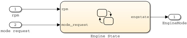
You model the mode sender port as a model root outport, which is mapped to an AUTOSAR mode sender port and a mode-switch (M-S) interface. The outport data type is an enumeration class with an unsigned integer storage type, representing an AUTOSAR mode declaration group.
In Simulink, you can:
Import AUTOSAR mode-switch communication elements from ARXML files.
The software imports ModeSwitchPoints, ModeSwitchInterfaces, and ModeDeclarationGroups.
For each AUTOSAR provider port that references an M-S interface, the importer creates a root outport with
ModeSenddata access and with an AUTOSAR mode declaration group enumeration class.The importer maps the model outport to an AUTOSAR mode sender port with an M-S interface.
Create AUTOSAR mode-switch communication elements.
Create a model root outport, and set the outport data type to an enumeration class that represents an AUTOSAR mode declaration group.
Create an AUTOSAR mode sender port with an associated M-S interface.
In the Code Mappings editor, set the outport data access mode to
ModeSend, and map the outport to the AUTOSAR mode sender port.
Generate ARXML files and C code for AUTOSAR mode sender ports and related AUTOSAR M-S communication elements.
The ARXML files include referenced ModeSwitchPoints, ModeSwitchInterfaces, and ModeDeclarationGroups.
The C code includes
Rte_SwitchAPI calls to communicate mode switches to other software components.
For more information, see Configure AUTOSAR Mode-Switch Communication.
Nonvolatile Data Interface
The AUTOSAR standard defines port-based nonvolatile (NV) data communication, in which an AUTOSAR software component reads and writes data to AUTOSAR nonvolatile components. To implement NV data communication, AUTOSAR software components define provide and require ports that send and receive NV data. For more information about modeling software component access to AUTOSAR nonvolatile memory, see Model AUTOSAR Nonvolatile Memory.
In Simulink, you can:
Import AUTOSAR NV data interfaces and ports from ARXML files.
Create AUTOSAR NV interfaces and ports, and map Simulink inports and outports to AUTOSAR NV ports.
You model AUTOSAR NV ports with Simulink inports and outports, in the same manner described in Sender-Receiver Interface.
Generate C code and ARXML files for AUTOSAR NV data interfaces and ports.
For more information, see Configure AUTOSAR Nonvolatile Data Communication.
Parameter Interface
The AUTOSAR standard defines port-based parameters for parameter communication. AUTOSAR
parameter communication relies on a parameter software component
(ParameterSwComponent) and one or more atomic software components that
require port-based access to parameter data. The ParameterSwComponent
represents memory containing AUTOSAR parameters and provides parameter data to connected
atomic software components.
In Simulink, you can model the receiver portion of AUTOSAR port-based parameter communication. In an AUTOSAR atomic software component, you create a parameter interface with data elements and a parameter receiver port.
For more information, see Configure AUTOSAR Port Parameters for Communication with Parameter Software Component.
Trigger Interface
The AUTOSAR standard defines external trigger event communication, in which an AUTOSAR
software component or service signals an external trigger occurred event
(ExternalTriggerOccurredEvent) to another component. The receiving
component activates a runnable in response to the event.
In Simulink, you can model the receiver portion of AUTOSAR external trigger event
communication. In a component that you want to react to an external trigger, you create a
trigger interface, a trigger receiver port to receive an
ExternalTriggerOccurredEvent, and a runnable that the event
activates.
For more information, see Configure Receiver for AUTOSAR External Trigger Event Communication.
See Also
Topics
- Configure AUTOSAR Sender-Receiver Communication
- Configure AUTOSAR Queued Sender-Receiver Communication
- AUTOSAR Client-Server Communication
- Configure AUTOSAR Mode-Switch Communication
- Configure AUTOSAR Nonvolatile Data Communication
- Configure AUTOSAR Port Parameters for Communication with Parameter Software Component
- Configure Receiver for AUTOSAR External Trigger Event Communication
- AUTOSAR Component Configuration