comm.GMSKDemodulator
Demodulate GMSK-modulated signal
Description
The comm.GMSKDemodulator
System object™ uses a Viterbi algorithm or maximum logarithmic a posteriori probability
(max-log-MAP) algorithm to demodulate a signal that was modulated using the Gaussian minimum
shift keying (GMSK) method. The input is a baseband representation of the modulated
signal.
To demodulate a GMSK-modulated signal:
Create the
comm.GMSKDemodulatorobject and set its properties.Call the object with arguments, as if it were a function.
To learn more about how System objects work, see What Are System Objects?
Creation
Description
gmskdemodulator = comm.GMSKDemodulator
gmskdemodulator = comm.GMSKDemodulator(Name,Value)comm.GMSKDemodulator(PulseLength=6) specifies the length of the
Gaussian pulse shape as 6 symbol intervals.
Properties
Usage
Description
Y = gmskdemodulator(X,nvar)Variance
property set to nvar. This syntax applies when you set VarianceSource
to 'Input port' and DecisionMethod
to 'Approximate log-likelihood ratio'.
Input Arguments
Output Arguments
Object Functions
To use an object function, specify the
System object as the first input argument. For
example, to release system resources of a System object named obj, use
this syntax:
release(obj)
Examples
Create a GMSK modulator and demodulator pair. Create an AWGN channel object.
gmskmodulator = comm.GMSKModulator( ...
    BitInput=true, ...
    InitialPhaseOffset=pi/4);
gmskdemodulator = comm.GMSKDemodulator( ...
    BitOutput=true, ...
    InitialPhaseOffset=pi/4);
channel = comm.AWGNChannel( ...
    NoiseMethod='Signal to noise ratio (SNR)', ...
    SNR=0);
Create an error rate calculator and account for the delay between the modulator and demodulator, caused by the Viterbi algorithm.
errorRate = comm.ErrorRate( ...
    ReceiveDelay=gmskdemodulator.TracebackDepth);
Process 100 frames of data looping through these steps.
Generate vectors with 300 elements of random binary data.
GMSK-modulate the data.
Pass the modulated data through the AWGN channel.
GMSK-demodulate the data.
Collect error statistics on the frames of data.
for counter = 1:100
   % Transmit 100 3-bit words
   data = randi([0 1],300,1);
   modSignal = gmskmodulator(data);
   noisySignal = channel(modSignal);
   receivedData = gmskdemodulator(noisySignal);
   errorStats = errorRate(data, receivedData);
end
Display the error statistics.
fprintf('Error rate = %f\nNumber of errors = %d\n', ...
         errorStats(1), errorStats(2))
Error rate = 0.000133
Number of errors = 4
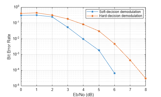
This example shows how to estimate bit error rate (BER) of a Gaussian minimum shift keying (GMSK) modulated signal with convolutional coding. Additionally, this example compares the BER performance for hard-decision and soft-decision Viterbi decoders in AWGN.
Set the samples per symbol, EbNo range and data length.
rng default
sps = 4;                  % Samples per symbol
EbNoVec = 0:10;           % Eb/No values (dB)
dataLen = 5e2;            % Number of input bits per iteration
Create a trellis structure for a rate 1/2 convolutional code with a constraint length of 4. Set the traceback depth for the Viterbi decoder to 20. Specify the coding rate as 1/2.
trellis = poly2trellis(4,[17 13]);
vitTB = 20;
rate = 1/2;
Initialize the comm.ConvolutionalEncoder and comm.ViterbiDecoder System objects.
cEnc = comm.ConvolutionalEncoder(TrellisStructure=trellis);
decoderHard = comm.ViterbiDecoder(TrellisStructure=trellis,InputFormat="hard",TracebackDepth=vitTB);
decoderSoft = comm.ViterbiDecoder(TrellisStructure=trellis,InputFormat="Unquantized",TracebackDepth=vitTB);
Initialize the comm.GMSKModulator and comm.GMSKDemodulator System objects. GMSK modulation can be represented using a trellis structure. Viterbi algorithm is used for hard demodulation and max-log-MAP BCJR algorithm is used for soft demodulation. For more information, see the Algorithms section of comm.GMSKDemodulator.
gmskTB = 6;
gmskMod = comm.GMSKModulator(BitInput=true, ...
    PulseLength=2, ...
    SamplesPerSymbol=sps, ...
    BandwidthTimeProduct=0.5);
gmskDemodHard = comm.GMSKDemodulator(BitOutput=true, ...
    PulseLength=2, ...
    TracebackDepth=gmskTB, ...
    SamplesPerSymbol=sps, ...
    BandwidthTimeProduct=0.5);
gmskDemodSoft = comm.GMSKDemodulator(BitOutput=true, ...
    PulseLength=2, ...
    TracebackDepth=gmskTB, ...
    DecisionMethod="Approximate log-likelihood ratio",...
    SamplesPerSymbol=sps, ...
    BandwidthTimeProduct=0.5);
Initialize the BER result vectors.
berSoft = comm.ErrorRate("ReceiveDelay",vitTB);
berHard = comm.ErrorRate("ReceiveDelay",vitTB);
[berEstSoft,berEstHard] = deal(zeros(size(EbNoVec)));
The main processing loop performs these steps:
Generate binary data
Encode the data using convolutional code
Interleave the encoded data to avoid the possibility of burst errors
Apply GMSK modulation to the data symbols.
Pass the modulated signal through an AWGN channel
Demodulate the received signal using hard decision and approximate LLR methods.
Deinterleave the demodulated bits
Viterbi decode the signals using hard and unquantized methods
Calculate the number of bit errors
The while loop processes data until it encounters 100 errors or transmits 2e5 bits.
for n = 1:length(EbNoVec)

    % Convert Eb/No to SNR
    snrdB = convertSNR(EbNoVec(n),'ebno',CodingRate=rate,SamplesPerSymbol=sps);

    % Noise variance calculation
    noiseVar = 10.^(-snrdB/10);

    % Reset the error and bit counters
    [numErrsSoft,numBits] = deal(0);

    gmskDemodSoft.Variance = noiseVar;

    while numErrsSoft < 100 && numBits < 2e5

        % Generate binary data
        dataIn = randi([0 1],dataLen,1);

        % Convolutionally encode the data
        dataEnc = cEnc(dataIn);

        % Interleave
        intrData = matintrlv(dataEnc,5,length(dataEnc)/5);

        % GMSK modulate
        txSig = gmskMod(intrData);

        % Pass through AWGN channel
        rxSig = awgn(txSig,snrdB,'measured');

        % Demodulate the noisy signal using hard decision (bit) and
        % soft decision (approximate LLR) approaches.
        demodHardOut = gmskDemodHard(rxSig);
        demodSoftOut = gmskDemodSoft(rxSig);

        if numBits > 0

        % Buffer data to account for delay
        deintrlvHardIn = [demHardBuffer(gmskTB+1:end);demodHardOut(1:gmskTB)];
        deintrlvSoftIn = [demSoftBuffer(gmskTB+1:end);demodSoftOut(1:gmskTB)];

        % Deinterleave
        deintHardOut =  matdeintrlv(deintrlvHardIn,5,length(dataEnc)/5);
        deintSoftOut =  matdeintrlv(deintrlvSoftIn,5,length(dataEnc)/5);

        % Viterbi decode
        dataHardOut = decoderHard(deintHardOut);
        dataSoftOut = decoderSoft(deintSoftOut);

        errHard = berHard(dataBuffer,dataHardOut);
        errSoft = berSoft(dataBuffer,dataSoftOut);

        % Store error counter
        numErrsSoft = errSoft(2);

        end

        numBits = numBits + dataLen;
        demHardBuffer = demodHardOut;
        demSoftBuffer = demodSoftOut;
        dataBuffer = dataIn;
    end
    release(cEnc)
    release(decoderHard)
    release(decoderSoft)
    release(gmskMod)
    release(gmskDemodHard)
    release(gmskDemodSoft)
    release(berSoft)
    release(berHard)

    % Log BER for both methods
    berEstSoft(n) = errSoft(1);
    berEstHard(n) = errHard(1);

end
Plot the estimated BER values for both hard and soft Viterbi decoding methods.
semilogy(EbNoVec,[berEstSoft;berEstHard],'-*')
hold on
legend('Soft-decision demodulation','Hard-decision demodulation','location','best')
grid
xlabel('Eb/No (dB)')
ylabel('Bit Error Rate')
Algorithms
References
[1] Anderson, John B., Tor Aulin, and Carl-Erik Sundberg. Digital Phase Modulation. New York: Plenum Press, 1986.
[2] Benedetto, S., G. Montorsi, D. Divsalar, and F. Pollara. "A Soft-Input Soft-Output Maximum A Posterior (MAP) Module to Decode Parallel and Serial Concatenated Codes." Jet Propulsion Lab TDA Progress Report (November 1996): 42–127.
[3] Viterbi, A.J. “An Intuitive Justification and a Simplified Implementation of the MAP Decoder for Convolutional Codes.” IEEE® Journal on Selected Areas in Communications 16, no. 2 (February 1998): 260–64. https://doi.org/10.1109/49.661114.