PN Sequence Generator
Generate pseudonoise sequence
Libraries:
Communications Toolbox /
Comm Sources /
Sequence Generators
Communications Toolbox HDL Support /
Comm Sources
Description
The PN Sequence Generator block generates a sequence of pseudorandom binary numbers using a linear-feedback shift register (LFSR). Pseudonoise sequences are typically used for pseudorandom scrambling, and in direct-sequence spread-spectrum systems. For more information, see More About.
These icons shows the block with all ports enabled.
![]()
![]()
Examples
Sequences output from the PN Sequence Generator block can be modeled using a linear feedback shift register (LFSR) built with primitive Simulink® blocks.
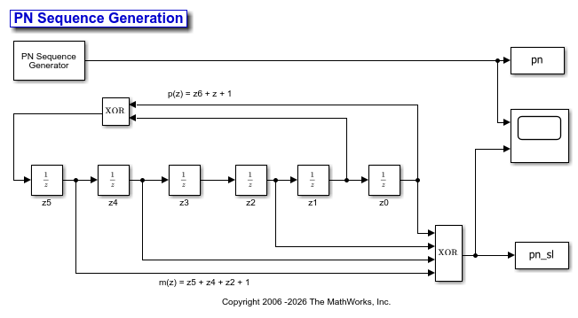
The cm_ex__pnseq_vs_prim_sl model generates the generator polynomial, p(z)=z^6+z+1, by using the PN Sequence Generator block and by modeling an LFSR using primitive Simulink blocks. The discrete block LFSR schematic model interprets the Initial states and Output mask vector (or scalar shift value) parameters of the PN Sequence Generator block. The PreLoadFcn callback function initializes runtime parameters. To view the callback functions from the Simulink Toolstrip, on the Modeling tab, in the Design gallery, click Property Inspector.
The scope output shows that the two implementations produce matching PN sequences.
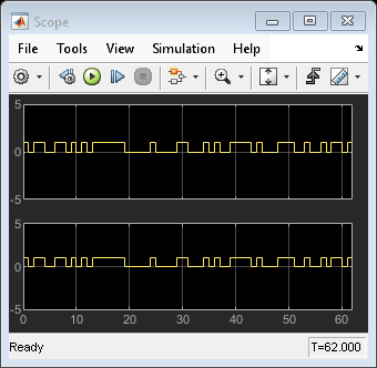
Using the PN Sequence Generator block allows you to easily generate PN sequences of large periods. To experiment further, open the model. Modify settings to see how the performance varies for different path delays or adjust the PN sequence generator parameters. You can experiment with different initial states by changing the value of Initial states before running the simulation. For all values, the two generated sequences are the same.
Digital communications systems commonly use additive scrambling and descrambling to randomize input data to aid in timing synchronization and meeting power spectral requirements. The Scrambler block supports multiplicative scrambling but does not support additive scrambling. To perform additive scrambling, you can use the PN Sequence Generator block. This example implements the additive scrambling specified in IEEE 802.11™ [1] by scrambling input data with an output sequence generated by the PN Sequence Generator block. For a MATLAB® example with a similar workflow, see the Additive Scrambling of Input Data example on the comm.PNSequence reference page.
This figure shows an additive scrambler, that uses the generator polynomial  , as specified in Figure 17-7 of IEEE 802.11™ Section 17.3.5.5 [1].
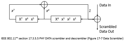
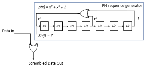
Compare the shift register specified in 802.11 with the shift register implemented using a PN Sequence Generator block and observe the two shift register schematics are mirror images of each other. Therefore, when configuring the PN Sequence Generator block to implement an additive scrambler, you must reverse values for the generator polynomial, the initial states, and the mask output. To take the output of the register from the leading end, specify a shift value of 7.
For more information about the 802.11 scrambler, see [1] and the wlanScramble (WLAN Toolbox) reference page.
The cm_additive_scrambling model scrambles and compares the generated scrambling sequence and a frame of data scrambled according to the 802.11 specified additive scrambler by using these two additive scrambler implementations:
A shift register comprised of discrete Delay (Simulink) blocks and Logical Operator (Simulink) blocks configured as XOR operators.
The PN Sequence Generator block and XOR operator.
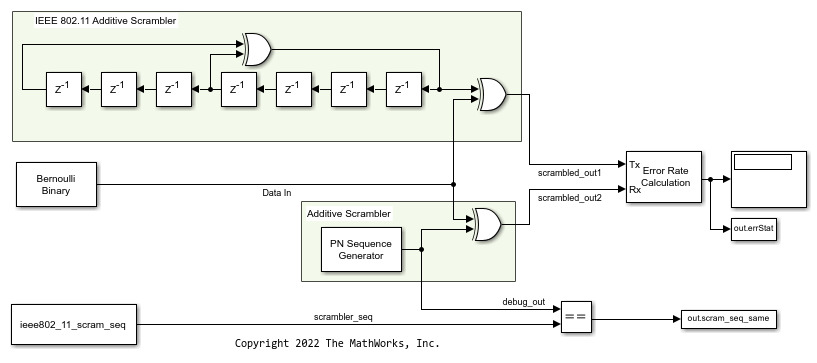
To compare the additive scrambler implementations, the cm_additive_scrambling model uses:
A Bernoulli Binary Generator block to provide an input signal to scramble.
A PN Sequence Generator block configured to use
 for the generator polynomial, [1 1 1 1 1 1 1] for the initial shift register state, and 7 for the output scrambling shift value.
A Logical Operator (Simulink) block configured as an XOR operator to apply the scramble sequence to the input data.
An Error Rate Calculation block to verify the scrambled data output from the discrete block shift register and the PN sequence versions of the additive scrambler match.
The
PreLoadFcncallback function to create a workspace variable containing the 127-bit scrambler output sequence specified in section 17.3.5.5 of the IEEE 802.11 standard. A Relational Operator (Simulink) configured for an==operation compares the 127-bit scrambler sequence as output from the Signal From Workspace block to the PN Sequence block output.
Simulate Additive Scrambling
Run the model and display the results of the error rate calculation for the scrambled input sequence and equal comparison for the scrambler sequence.
Number of errors in scrambled output comparison is 0.
Number of mismatches comparing PN sequence output to IEEE 802.11 scrambler sequence 0.
References
[1] IEEE Std 802.11™-2020 (Revision of IEEE Std 802.11-2016). "Part 11: Wireless LAN Medium Access Control (MAC) and Physical Layer (PHY) Specifications." IEEE Standard for Information technology - Telecommunications and information exchange between systems. Local and metropolitan area networks - Specific requirements.
This model simulates pseudo-random spreading for a single-user system in a multipath transmission environment. This is similar to a mobile channel environment where the signals are received over multiple paths. Each path can have different amplitudes and delays. The receiver combines the independent paths coherently by using diversity reception to realize gains from the multipath transmissions received. The modeled system does not simulate fading effects and the receiver gets perfect knowledge of the number of paths and their respective delays.
The model uses random binary data, which is BPSK modulated (real), spread by PN sequences, and then transmitted over a multipath AWGN channel. The receiver consists of a despreader, a diversity combiner, and a BPSK demodulator. The receiver achieves gains from diversity combining due to the ideal auto-correlation properties of the PN sequences used when spreading the data.
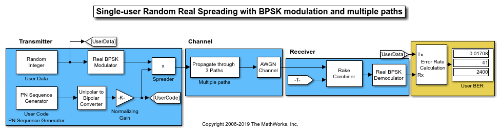
To experiment further, open the model. Modify the settings to see how the performance varies for different path delays or adjust the PN sequence generator parameters.
This model simulates pseudo-random spreading for two users in a multipath transmission environment. This is similar to a mobile channel environment where the signals are received over multiple paths. Each path can have different amplitudes and delays. The receiver combines the independent paths coherently using diversity reception to realize gains from the multipath transmissions received. The modeled system does not simulate fading effects and the receiver gets perfect knowledge of the number of paths and their respective delays.
The model uses random binary data, which is BPSK modulated (real), spread by PN sequences, and then transmitted over a multipath AWGN channel. The receiver consists of a despreader, a diversity combiner, and a BPSK demodulator.
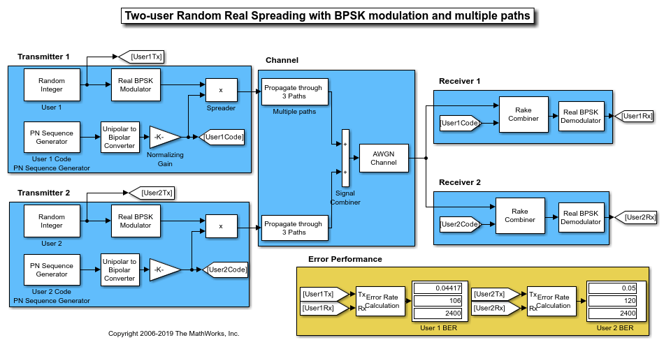
Using the same transmission data, the model calculates the performance for two-user transmissions through identically configured, multipath AWGN channels.
Because the transmissions for the individual users were spread using different PN sequences, the error rate computed for the users are different. Due to the higher cross-correlation properties of the nonorthogonal PN sequences used to spread the data, BER performance is degraded in a multipath environment. Sequences with high orthogonality, such as Hadamard and Kasami, are a better choice for multipath environments. For a multipath example that uses Hadamard code sequences when spreading user data, see Orthogonal Spreading for Multiuser System in Single-Path Channel. For a multipath example that uses Kasami code sequences when spreading user data, see Kasami Spreading for Multiuser System in Multipath Channel.
To experiment further, open the model. Modify the settings to see how the performance varies for different path delays or with different PN sequences for the individual users.
Ports
Input
Output
Parameters
Block Characteristics
Data Types |
|
Multidimensional Signals |
|
Variable-Size Signals |
|
More About
A linear-feedback shift register (LFSR), implemented as a simple shift register generator (SSRG), is used to generate PN sequences. This type of shift register is also known as a Fibonacci implementation.
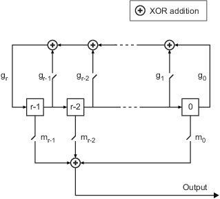
The polynomial g determines the feedback connections of the shift register. It is a primitive binary polynomial in z, grzr+gr–1zr–1+gr–2zr–2+...+g0. For the coefficient gk=0 to r, the coefficient gk is 1 if there is a connection from the kth register to the adder. The leading term, gr, and the constant term, g0, of the generator polynomial must be 1 because the polynomial must be primitive. At each time step, all r registers in the generator update their values according to the value of the incoming arrow to the shift register. The adders perform addition modulo 2. The output of the LFSR reflects the sum of all connections in the m mask vector.
g is specified by the Generator polynomial parameter.
The initial value of r is specified by the Initial states parameter.
m determines the shift of the PN sequence starting point and is specified by the Output mask vector (or scalar shift value) parameter or Mask port.
This table indicates two sets of parameter values that correspond to the generator polynomial g(z) = z8 + z2 + 1.
| Quantity | Example 1 | Example 2 |
|---|---|---|
| g | g1 = [1 0 0 0 0 0 1 0 1] | g2 = [8 2 0] |
| Degree of generator polynomial, g | 8, which is length(g1)-1
| 8 |
| Initial states | [1 0 0 0 0 0 1 0] | [1 0 0 0 0 0 1 0] |
For an example, see Model PN Sequence Generation with Linear Feedback Shift Register.
Before you can reset the generator sequence, you must select the
Reset on nonzero input parameter to enable the
Rst input port. Suppose that the PN Sequence Generator block outputs
[1 0 0 1 1 0 1 1] when no reset exists. This table shows the effect
on the PN Sequence Generator block output for the parameter values indicated.
| Reset Signal | Reset Signal Settings | PN Sequence Generator block | Reset Signal and Output Signal |
|---|---|---|---|
| No reset |
|
|
|
| Scalar reset signal |
|
|
|
| Vector reset signal |
|
|
For the no-reset case, the block outputs the sequence without resetting it.
For the scalar and vector reset signal cases, the block inputs the reset signal [0
0 0 1 0 0 0 0] to the Rst port. Because the fourth bit of
the reset signal is a 1 and Sample time is
1, the block resets the sequence output at the fourth bit.
For variable-sized outputs, the block supports only scalar reset signal inputs.
References
[1] Proakis, John G. Digital Communications. 5th ed. New York: McGraw Hill, 2007.
[2] Lee, J. S., and L. E. Miller. CDMA Systems Engineering Handbook. Boston and London. Artech House, 1998.
[3] Golomb, S.W. Shift Register Sequences. Laguna Hills. Aegean Park Press, 1967.