Analog Baseband Modulation
In most media for communication, only a fixed range of frequencies is available for transmitting messages. One way to communicate a message signal whose frequency spectrum does not fall within that fixed frequency range, or one that is otherwise unsuitable for the channel, is to alter a transmittable signal according to the information in your message signal. This alteration is called modulation. The transmitter sends the modulated symbols. The receiver then recovers the original message symbols through a process called demodulation.
Modulation Methods
Analog baseband modulation modulates analog signals into sinusoidal waveforms. Communications Toolbox™ software provides features to apply a variety of analog baseband modulation methods. The process by which a carrier signal is altered according to information in a message signal depends on the modulation method applied. The general form of the carrier signal, s(t), as:
s(t) = A(t)cos[2πf0t+ϕ(t)]
The information-carrying component is the amplitude (A), frequency (f0), or phase (ϕ) individually, or in combination. To satisfy the Nyquist criterion when simulating analog modulation systems, the sample rate of the system must be greater than twice the sum of the carrier frequency and the signal bandwidth. For more information, see Baseband vs. Passband Simulation.
| Functions | System objects | Blocks |
|---|---|---|
None | FM Modulator Baseband, FM Demodulator Baseband FM Broadcast Modulator Baseband, FM Broadcast Demodulator Baseband |
FM
Analog baseband FM modulates using frequency modulation. The output is a baseband representation of the modulated signal. The output signal's frequency varies with the input signal's amplitude. Both the input and output signals are real scalar signals.
If the input is u(t) varying as a function of time t, then the output is
where
fc represents the carrier frequency.
θ represents the initial phase.
Kc represents the frequency deviation.
Typically, an appropriate carrier frequency is a much higher than the highest frequency of the input signal. By the Nyquist sampling theorem, 1 / Ts > (2 × fc), where Ts represents the sample time of the input signal. For more information, see Baseband vs. Passband Simulation.
FM Broadcast
Analog baseband FM broadcast includes the functionality of the baseband FM modulator, plus pre-emphasis filtering and the ability to transmit stereophonic signals.
Filtering
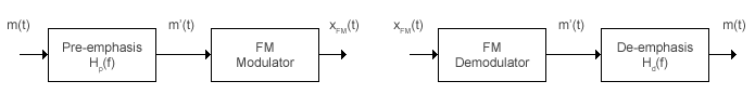
FM amplifies high-frequency noise and degrades the overall signal-to-noise ratio. To compensate, FM broadcasters insert a pre-emphasis filter before FM modulation to amplify the high-frequency content. The FM receiver has a reciprocal de-emphasis filter after the FM demodulator to attenuate high-frequency noise and restore a flat signal spectrum. This figure shows the order of processing operations.
The pre-emphasis filter has a highpass characteristic transfer function given by
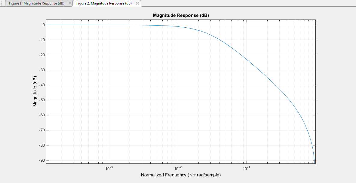
where τs is the filter time constant. The time constant is 75 μs in the United States and 50 μs in Europe. Similarly, the transfer function for the lowpass de-emphasis filter is given by
For an audio sample rate of 44.1 kHz, the de-emphasis filter has the response shown in this figure.
Multiplexed Stereo and RDS (or RBDS) FM Signal
FM broadcast supports stereophonic and monophonic operations. To support stereo transmission:
The Left + Right channel information is assigned to the mono portion of the spectrum (0 to 15 kHz).
The Left – Right channel information is amplitude modulated onto the 23 to 53 kHz region of the baseband spectrum using a 38 kHz subcarrier signal.
A pilot tone at 19 kHz in the multiplexed signal enables the FM receiver to coherently demodulate the stereo and RDS (or RBDS) signals.
This figure shows the spectrum of the multiplex baseband signal.

The multiplex message signal m(t) is given by
where C0, C1, and C2 are gains. To generate the appropriate modulation level, these gains scale the amplitudes of the L(t)±R(t) signals, the 19 kHz pilot tone, and the RDS (or RBDS) subcarrier, respectively.
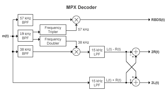
The demodulator applies m(t) to three bandpass filters with center frequencies at 19, 38, and 57 kHz and to a lowpass filter with a 3 dB cutoff frequency of 15 kHz. The 19 kHz bandpass filter extracts the pilot tone from the modulated signal. The recovered pilot tone is doubled and tripled in frequency to produce the 38 kHz and 57 kHz signals, which demodulate the (L – R) and RDS (or RBDS) signals, respectively. To generate a scaled version of the left and right channels that produces the stereo sound, the object adds and subtracts the (L + R) and (L – R) signals. To recover the RDS (or RBDS) signal, m(t) is mixed with the 57 kHz signal.
This figure shows the multiplexing (MPX) decoder block diagram of the FM broadcast demodulator. L(t) and R(t) are the left and right audio signal components of the time-domain waveforms. RBDS(t) is the time-domain waveform of the RDS (or RBDS) signal.
Accessing Analog Baseband Modulation Blocks
In Simulink®, open the Analog Baseband Modulation sublibrary by double-clicking its icon in the Modulation library. The Analog Baseband Modulation sublibrary contains modulator-demodulator block pairs for these modulation methods.
| Block Pair | Modulation Method |
|---|---|
FM Broadcast Modulator Baseband, FM Broadcast Demodulator Baseband | Frequency modulation broadcast |
| Frequency modulation |
References
[1] Hatai, I., and I. Chakrabarti. “A New High-Performance Digital FM Modulator and Demodulator for Software-Defined Radio and Its FPGA Implementation.” International Journal of Reconfigurable Computing (December 25, 2011): 1–10. https://doi.org/10.1155/2011/342532.
[2] Taub, H., and D. Schilling. Principles of Communication Systems. McGraw-Hill Series in Electrical Engineering, 142–55. New York: McGraw-Hill, 1971.