CIC Interpolator
Libraries:
DSP HDL Toolbox /
Filtering
Description
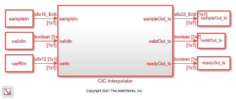
The CIC Interpolator block interpolates an input signal by using a cascaded integrator-comb (CIC) interpolation filter. CIC interpolation filters are a class of linear phase finite impulse response (FIR) filters consisting of a comb part and an integrator part. The CIC interpolation filter structure consists of N sections of cascaded comb filters, a rate change factor of R, and N sections of cascaded integrators. For more information about CIC interpolation filters, see Algorithms.
The block supports these combinations of input and output data.
Scalar input and scalar output — Support for fixed and variable interpolation rates
Scalar input and vector output — Support for fixed interpolation rates only
Vector input and vector output — Support for fixed interpolation rates only
The block provides an architecture suitable for HDL code generation and hardware deployment.
Note
You can also generate HDL code for this hardware-optimized algorithm, without creating a Simulink® model, by using the DSP HDL IP Designer app. The app provides the same interface and configuration options as the Simulink block.
Examples
Implement CIC Interpolator Filter for HDL
Filter and upsample data by using the CIC Interpolator block.

Implement Digital Upconverter for FPGA
Design a digital upconverter (DUC) for LTE on FPGAs.
Ports
Input
Output
Parameters
Tips
Reset Behavior
By default, the CIC Interpolator block connects the generated HDL global reset to only the control path registers. The two reset parameters, Enable reset input port and Use HDL global reset, connect a reset signal to the data path registers. Because of the additional routing and loading on the reset signal, resetting data path registers can reduce synthesis performance.
The Enable reset input port parameter enables the reset port on the block. The reset signal implements a local synchronous reset of the data path registers. For optimal use of FPGA resources, this option does not connect the reset signal to registers targeted to the DSP blocks of the FPGA.
The Use HDL global reset parameter connects the generated HDL global reset signal to the data path registers. This parameter does not change the appearance of the block or modify simulation behavior in Simulink. The generated HDL global reset can be synchronous or asynchronous depending on the HDL Code Generation > Global Settings > Reset type parameter in the model Configuration Parameters. Depending on your device, using the global reset might move registers out of the DSP blocks and increase resource use.
When you select the Enable reset input port and Use HDL global reset parameters together, the global and local reset signals clear the control and data path registers.
Reset Considerations for Generated Test Benches
FPGA-in-the-loop (FIL) initialization provides a global reset but does not automatically provide a local reset. With the default reset parameters, the data path registers that are not reset can result in FIL mismatches if you run the FIL model more than once without resetting the board. Select Use HDL global reset to reset the data path registers automatically, or select Enable reset input port and assert the local reset in your model so the reset signal becomes part of the Simulink FIL test bench.
The generated HDL test bench provides a global reset but does not automatically provide a local reset. With the default reset parameters and the default register reset Configuration Parameters, the generated HDL code includes an initial simulation value for the data path registers. However, if you are concerned about
X-propagation in your design, you can set the HDL Code Generation > Global Settings > Coding style > No-reset registers initialization parameter in Configuration Parameters toDo not initialize. In this case, with the default block reset parameters, the data path registers that are not reset can causeX-propagation on the data path at the start of HDL simulation. Select Use HDL global reset to reset the data path registers automatically, or select Enable reset input port and assert the local reset in your model so the reset signal becomes part of the generated HDL test bench.
Algorithms
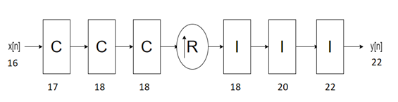
The CIC Interpolator block has the CIC filter structure shown in this figure. The structure consists of N sections of cascaded comb filters, a rate change factor of R, and N sections of cascaded integrators [1].
You can locate the unit delay in the integrator part of the CIC filter in either the feedforward or feedback path. These two configurations yield an identical filter frequency response. However, the numerical outputs from these two configurations are different due to the latency of the block. Because this configuration is preferred for HDL implementation, this block puts the unit delay in the feedforward path of the integrator.
The block outputs data based on the output data type selection. Consider a block with R, M, and N values of 8, 1, and 3, respectively, and an input width of 16. The word length at the ith internal stage is calculated as , where:
Gi is the gain at ith stage.
BIn is the input word length.
Bi is the word length at ith stage.
The output word length is calculated as , where BOut is the output word length.
When you set the Output data type parameter to Full
precision, the block outputs data with a word length of 22 by adding 6 gain
bits to the input word length of 16. The word lengths of the internal comb and integrator
stages are set to accommodate the bit growth.
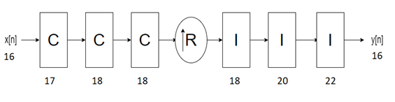
When you set the Output data type parameter to Same
word length as input, the block outputs data with a word length of 16, which
is the same length as the input word length. The word lengths of the internal comb and
integrator stages are set in the same way as in Full precision
mode.
When you set the Output data type parameter to Minimum
section word lengths and the Output word length
parameter to 16, the block outputs data with a word length of 16. The
word lengths of the internal comb and integrator stages are set in the same way as in
Full precision mode.
The latency of the block changes depending on the type of input, the interpolation you specify, the number of sections, the value of the Gain correction parameter, and the value of the Minimum number of cycles between valid input samples parameter. This table shows the latency of the block. N is the number of sections, vecLen is the length of the vector, and R is the interpolation factor.
| Input Data | Output Data | Interpolation Type | Gain Correction | Minimum number of cycles between valid input samples (NumCycles) | Latency in Clock Cycles |
|---|---|---|---|---|---|
| Scalar | Scalar | Fixed | off | NumCycles is equal to R or greater than R |
|
on | NumCycles is equal to R or greater than R |
| |||
| Scalar | Vector | Fixed | off | NumCycles is equal to 1 or less than R | 4 + N + ((R x vecLen) + 2) x N. |
on | NumCycles is equal to 1 or less than R | 4 + N + ((R x vecLen) + 2) x N + 9. | |||
| Vector | Vector | Fixed | off | NumCycles is equal to 1 |
|
on | NumCycles is equal to 1 |
|
Note
The block does not support variable interpolation for these two combinations of input and output:
Scalar input and vector output
Vector input and vector output
This section shows the output of the block for a scalar input with different R, M, and N values.
This figure shows the output of the block with the default configuration (that is, with a fixed interpolation rate and R, M, and N values of 2, 1, and 2, respectively). The latency of the block is 5 clock cycles and is calculated as 3 + N, where N is the number of sections.

This figure shows the output of the block with a fixed interpolation rate, R, M, and N values of 8, 1, and 3, respectively, and the Gain correction parameter selected. The latency of the block is 15 clock cycles and is calculated as 3 + N + 9, where N is the number of sections.

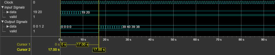
This section shows the output of the block for a vector input with different R, M, and N values.
This figure shows the output of the block for a two-element column vector input with the default configuration (that is, with a fixed interpolation rate and R, M, and N values of 2, 1, and 2, respectively). The latency of the block is 17 clock cycles.
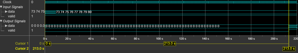
This figure shows the output of the block for an eight-element column vector input with a fixed interpolation rate, R, M, and N values of 8, 1, and 3, respectively, and the Gain correction parameter selected. The latency of the block is 213 clock cycles.
References
[1] Hogenauer, E. “An Economical Class of Digital Filters for Decimation and Interpolation.” IEEE Transactions on Acoustics, Speech, and Signal Processing 29, no. 2 (April 1981): 155–62. https://doi.org/10.1109/TASSP.1981.1163535.
Extended Capabilities
Version History
Introduced in R2022a