Verify Numerical Accuracy using Processor-in-The-Loop (PIL)
Using PIL
In a processor-in-the-loop (PIL) simulation, the generated code runs on a QEMU emulating the ARM® Cortex®-M processor. The results of the PIL simulation are transferred to Simulink® to verify the numerical equivalence of the simulation and the code generation results. The PIL verification process is a crucial part of the design cycle to check that the behavior of the generated code matches the design. For more information, see Code Verification and Validation with PIL.
Perform PIL Verification Using the PIL Block
This example shows how to create a PIL block from a Subsystem block that contains the model that you want to verify. It then shows how to verify numerical equivalence by comparing the signals of the two blocks.
With this approach:
You can verify code generated for subsystems.
You must provide a test harness model to supply test vector or stimulus inputs.
You must swap your original subsystem with a generated PIL block. Do not save your model in this state, or you will lose your original subsystem.
For more information, see Choose a SIL or PIL Approach.
Tip
To better understand this process, look at “Task 1 - Verify generated code using PIL block” in Code Verification and Validation with PIL.
Create a Subsystem and a PIL block from the model that you want to test:
Create a model, called the “test harness model”, and configure it for the ARM Cortex-M3, M4, M55 and M7 processors (QEMU), as described in Build and Run Executable on ARM Cortex-Mx processor.
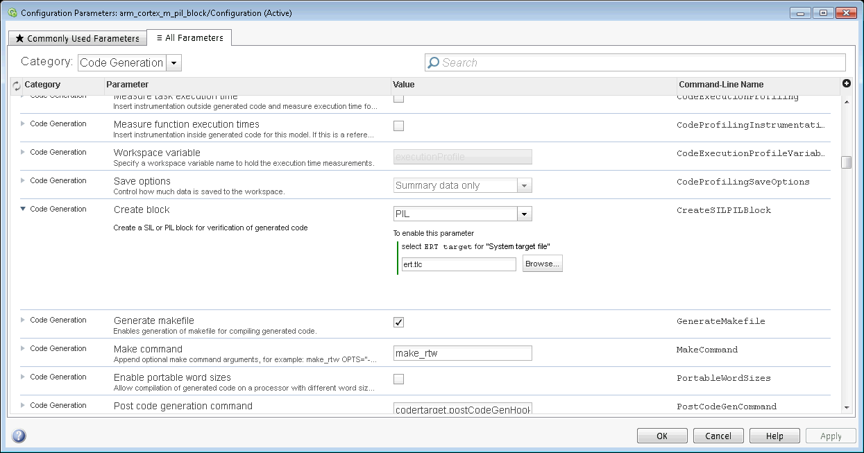
Set Configuration Parameters > All Parameters > Create block to PIL. Then, click OK.

Add a Subsystem block to the test harness model.
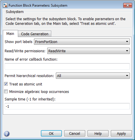
Right-click the Subsystem block and select Block Parameters (Subsystem).
In the dialog box, select Treat as atomic unit.

Place or create the model that you want to test within the Subsystem block.
Right-click the Subsystem block and select C/C++ Code > Build This Subsystem.

In the Build code for Subsystem dialog box, click Build.

This action creates an
untitled*model that contains a PIL block named after the subsystem.Copy the PIL block from
untitled*to the test harness model.Close
untitled*without saving it.
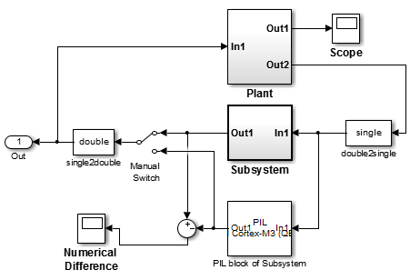
Create a test harness around the Subsystem and PIL blocks.

To create a test harness, you can:
Use parallel inputs for the Subsystem and PIL blocks.
Use a Sum block to compare the outputs for differences.
Connect the output of the Sum block to a Scope block to display the numerical differences.
Use a Manual Switch block to toggle between the outputs of the two blocks
Run the PIL simulation:
Leave Simulation mode set to
Normal.
Click Run.

This action simulates the test harness model in Simulink software. It runs the PIL block on the ARM Cortex-M3 QEMU. The simulation lasts for the duration specified by the Simulation stop time.
During the simulation, you can:
Use the Manual Switch to toggle between the two outputs.
Observe the scope for numerical differences.
Perform PIL Verification Using Model Block PIL
This example shows how to run two model blocks, one in normal simulation, and the other in PIL simulation, to verify that their outputs are numerically equivalent.
With this approach:
You can verify code generated for referenced models.
You must provide a test harness model to supply test vector or stimulus inputs.
You can easily switch a model block between the normal and PIL simulation mode
For more information, see Model.
Tip
To better understand this process, look at “Task 2 - Verify generated code using PIL Simulation for Model Blocks” in Code Verification and Validation with PIL.
Create the model that you want to verify, called the “referenced model”.
Create a model to run the PIL simulation, called the “test model”.
Configure both the referenced model and the test model for the ARM Cortex-M3 (QEMU), as described in Build and Run Executable on ARM Cortex-Mx processor.
You must maintain the same model Configuration Parameter values for both the referenced model and the test model. You can share a configuration between the two models, as described in Share a Configuration with Multiple Models.
Add a Model block to the test model that points to your referenced model, as described in Reference Existing Models.
Copy and paste the Model block so the test model contains two identical Model blocks.
Create parallel inputs and outputs for the Model blocks.
To see an example model of this type, enter
arm_cortex_m_model_pil_blockin a MATLAB® Command Window.
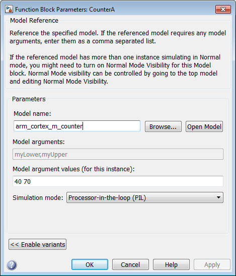
Right-click one of the Model blocks, and select Block Parameters (ModelReference).

In the Function Block Parameters dialog box, set Simulation mode to
Processor-in-the-loop, and click OK.
Leave the Simulation mode of the test model and the other Model block set to
Normal.
Click Build, Deploy & Start.

This action simulates the test model and one Model block in Simulink software. It runs the Model block that you configured to use PIL on the ARM Cortex-M3 QEMU. The simulation lasts for the duration specified by the Simulation stop time.
Perform PIL Verification Using PIL Simulation for Top Models
This example shows you how to record PIL simulation data from your model, and then review it using the Simulation Data Inspector.
With this approach:
You can verify code generated for a top model.
You must configure the model to load test vectors or stimulus inputs from the MATLAB workspace.
You can switch the entire model between normal and PIL simulation mode.
Tip
To better understand this process, look at “Task 3 - Verify generated code using PIL simulation for top models” in Code Verification and Validation with PIL.
Create the model that you want to verify, called the “test model”, and configure it for the ARM Cortex-M3 (QEMU), as described in Build and Run Executable on ARM Cortex-Mx processor.
To see an example model of this type, enter
arm_cortex_m_top_model_pilin a MATLAB Command Window.
Go to Apps tab and select the SIL/PIL Manager.
Select
Processor-in-the-Loopin the SIL/PIL Mode.
Click on Run Verification.
This action simulates the test model in PIL mode on the ARM Cortex-M3 QEMU. The simulation lasts for the duration specified by the Simulation stop time.
When the PIL simulation stops, go to Simulation tab and click the Data Inspector button to open the Simulation Data Inspector and review the PIL data. For more information, refer to Simulation Data Inspector