Introduction to ASAP2 File
The ASAM MCD-2 MC standard, also known as ASAP2, is a data definition standard proposed by
the Association for Standardization of Automation and Measuring Systems (ASAM). ASAP2 is a
non-object-oriented description of the data used for measurement, calibration, and diagnostic
systems. For more information on ASAM and the ASAM MCD-2 MC (ASAP2) standard, see the ASAM
website at www.asam.net.
To make use of ASAP2 file generation and customization, you should become familiar with:
ASAM and the ASAP2 standard and terminology. See the ASAM Web site at
www.asam.net.Configuring model data elements for code generation. See Code Mappings Editor – C.
Storage and representation of signals and parameters in generated code. See Data Representation in Generated Code.
Using the Generate Calibration Files tool.
Adding custom data elements to the ASAP2 file. See Create and Add Custom Data Elements.
Define System Target File to Generate ASAP2 File
You can generate an ASAP2 file with varying system target file configurations. For
example, ERT-based, GRT-based, Simulink Real-Time, AUTOSAR Classic, or AUTOSAR Adaptive
system target configurations allow you to generate an ASAP2 file by using the Generate Calibration Files tool or
the coder.asap2.export function.
Define ASAP2 Information for Signals and Parameters
Information about parameters and signals in your model is required to generate an ASAP2
file. Use the Model Data Editor and built-in Simulink® data objects to provide information, such as using Simulink.Signal
objects to provide measurement information and Simulink.Parameter
objects to provide characteristic information. You can also use data objects from data
classes that are derived from Simulink.Signal and
Simulink.Parameter to provide this information.
For more information, see Data Objects and Model Data Editor.
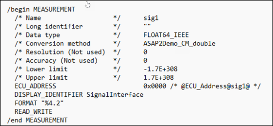
A Simulink.Signal is generated as Measurement in
the ASAP2 file.
A Simulink.Parameter is generated as
Characteristic in the ASAP2 file.

Define ASAP2 Information for Lookup Tables
Simulink
Coder™ software generates ASAP2 descriptions for lookup table data and its
breakpoints. The software represents 1-D table data as CURVE information,
2-D table data as MAP information, and breakpoints as
AXIS_DESCR and AXIS_PTS information. You can model
lookup tables by using one of these Simulink Lookup Table blocks:
The software supports these types of lookup table breakpoints (axis points).
| Breakpoint Type | Information Generated |
|---|---|
| Tunable and shared among multiple table axes (common axis) |
|
| Fixed and nontunable (fixed axis) | One of these variants of
|
| Tunable but not shared among multiple tables (standard axis) |
|
When you configure the blocks for ASAP2 code generation:
To configure a standard axis, use a n-D Lookup Table block. Use a
Simulink.LookupTableobject for table data and specify the Breakpoint Specification block parameter asExplicit values.To configure a common axis, use an Interpolation Using Prelookup block and use a
Simulink.LookupTableobject in the table data.For the
Simulink.LookupTableobject, specify Breakpoint Specification asReference.For breakpoints, use Prelookup blocks and table data using
Simulink.Breakpointobjects.
To configure a fixed axis, use an n-D Lookup Table block. Use a
Simulink.Lookuptableobject for table data and specify the Breakpoint Specification block parameter asEven Spacing.For ASAP2 version 1.31 and earlier, the breakpoints must be stored as integers in the code. The data type must be a built-in integer type (
int8,int16,int32,uint8,uint16, oruint32), a fixed-point data type, or an equivalent alias type.For ASAP2 version 1.6 and later, the breakpoints can be stored as floating-point types in the code.
Here is an example of an n-D Lookup Table record generated into an ASAP2 file in Standard Axis format.

Structure of ASAP2 File
This table outlines the basic structure of the ASAP2 file and describes the customization functions used to create each part of the file.
Static parts of the ASAP2 file are shown in bold.
Use the
coder.asap2.UserCustomizeBasefunction to add custom data to the ASAP2 file.
File Section | Function to update the section |
|---|---|
File header | HeaderComment |
| AfterBeginProjectContents |
| AfterBeginHeaderContents |
|
|
| AfterBeginModuleContents |
| |
Model-dependent | |
| coder.asap2.AxisInfo |
| coder.asap2.Characteristic |
| coder.asap2.CompuMethod |
| coder.asap2.Function |
| coder.asap2.Group |
| coder.asap2.Measurement |
| coder.asap2.RecordLayout |
| |
|
|
File footer/tail | writeFileTail |
For an example about how to generate an ASAP2 file from a Simulink model, see Generate ASAP2 and CDF Data Definition Files.
For more answers to questions about ASAP2 file generation, see Frequently Asked Questions About ASAP2 File Generation.
See Also
Generate Calibration Files | coder.asap2.export | coder.asap2.UserCustomizeBase