Getting Started with VxWorks 7 on AMD Zynq Boards
This example shows how to generate and run code from a Simulink® model onto an AMD Zynq® ZC702 evaluation kit with a VxWorks® 7 operating system.
Introduction
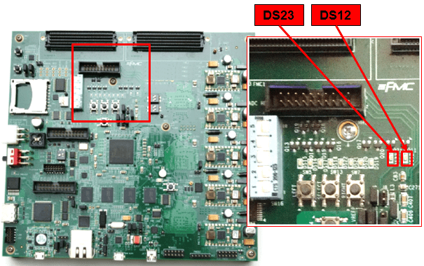
Embedded Coder® Support Package for AMD SoC Devices lets you generate code from Simulink models and run the executable on Zynq boards. The Simulink model can be configured to generate code for different operating systems that can be running on the Zynq boards. This example shows how to generate code from a Simulink model and run the compiled model on a AMD Zynq ZC702 evaluation kit that uses a VxWorks 7 operating system. The example model will blink the DS12 and DS23 LEDs on the ZC702 hardware board.
Requirements
Create System Object
Run the ZC702LEDS M script to create the system object that is used by the model.
run('ZC702LEDS');Open and Inspect the Model
Open the Getting Started with VxWorks on Zynq hardware model. The model has been configured to use the VxWorks operating system.
open_system('zynq_vxworks_gsg');
You can inspect the operating system configuration of the model as follows.
On the Hardware tab, click Hardware Settings.
On the Configuration Parameters > Code Generation tab, Build process > Toolchain Settings > Toolchain is set to
Wind River Workbench DIAB 5.9.4.0.On the Configuration Parameter > Hardware Implementation tab, Hardware board settings > Operating system/scheduler > Operating system is set to
VxWorks.
Build and Run the Model
Connect the AMD Zynq ZC702 evaluation kit to the host computer.
Setup a TFTP file sharing connection between the host computer and the AMD Zynq ZC702 evaluation kit. For instructions on setting up a TFTP/WFTPD file sharing connection, see TFTP/WFTPD Configuration Guide.
In the Hardware tab, click Build, Deploy, & Start to build model and run the compiled model on the hardware board. The generated code will be compiled and linked on the host computer to create the VxWorks 7 executable. The generated code and executable are saved to the TFTP directory.
When the code starts running on the Zynq board the
DS12andDS23LEDs on the board start blinking at different rates. TheDS12LED is on for 0.25 second and off for 0.25 second. Similarly,DS23LED is on for 0.5 second and off for 0.5 second.

Start and Stop Model Running on the Zynq Hardware Board
To run/stop a Simulink model, you use the runModel and stopModel methods of the Zynq VxWorks Kernel Shell communication object.
1. Create a communication object to the Zynq board using the zynq function. Zynq VxWorks Kernel Shell object that is your gateway to communicating with your Zynq hardware from MATLAB® command window.
zvxworks = zynq('vxworks')
2. Check if the getting started model is running using the following code. If the model is running, the function returns true.
isrunning(zvxworks, 'zynq_vxworks_gsg')
3. To stop the model started in the previous section, run the following on the MATLAB command window. You should see DS12 and DS23 LEDs stop blinking at this point. You can also use the isModelRunning method to test if the model has stopped.
stop(zvxworks, 'zynq_vxworks_gsg')
4. To start a previously built model on your hardware board, you use runModel method. In order to start the Getting Started with VxWorks on Zynq hardware model again, run the following on the MATLAB command window.
runModel(zvxworks, 'zynq_vxworks_gsg')
Other Things to Try
Modify the other example models in the Embedded Coder Support Package for AMD SoC Devices to use the VxWorks operating system.