Enable-Based Multicycle Path Constraints
Multicycle path (MCP) constraints relax timing requirements for register-to-register paths that need more than one clock cycle for data propagation. These constraints are critical for multirate designs or slow paths where the single-cycle timing assumption can cause violations. Without MCP constraints, synthesis tools assume all registers operate at the primary clock rate and expect data to transfer within one cycle, which can lead to timing failures during synthesis. You can use enable-based MCP constraints to enable synthesis tools to understand that certain paths can take multiple cycles.
Use MCP constraints to preserve the original architecture without adding pipeline stages. MCP constraints also help you meet timing for oversampled designs or designs with long combinational paths.
How Enable-Based MCP Constraints Work
When your Simulink® model includes multiple sample rates or uses speed and area optimizations that insert pipeline registers, the design can contain multicycle paths. A multicycle path is a data path between two registers that operate at a sample rate slower than the FPGA clock rate, requiring multiple clock cycles to complete execution. To align the FPGA clock with the sample rates of different paths, HDL Coder creates a timing controller to manage slower paths. The timing controller produces clock-enable signals with the required rate and phase information to control sequential elements, such as Delay blocks, that run at different sample rates.
The diagram shows two registers, REGA and
REGB. The data path Multicycle Path
connects the registers. The Multicycle Path element represents
long combinational logic or a slow path that cannot complete in one clock cycle.
Both registers share the same primary clock but operate at a slower effective rate
using clock enable signals.
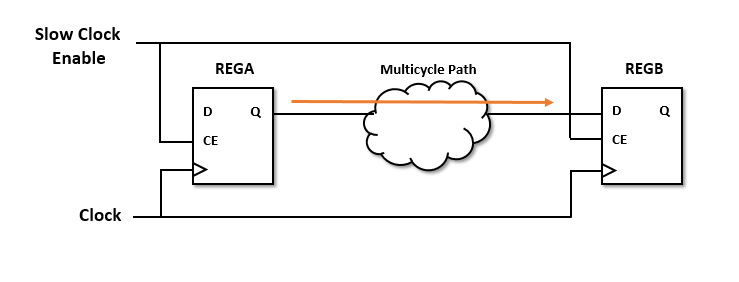
Synthesis tools require that data propagates from a source register to a
destination register in one clock cycle. Multicycle path constraints relax this
timing requirement by allowing multiple clock cycles for data to propagate between
the registers. The code generator uses the timing controller enable signals to
create enable-based register groups, where one clock enable drives the registers in
each group. When you apply the enable-based constraints and generate HDL code, the
code generator outputs a constraints file with the naming convention
dutname_constraints. The file defines the timing requirements
of multicycle paths and contains information about the setup and hold
constraints.
This figure shows a multicycle path that takes a number of clock cycles,
N, for the data to propagate from
REGA to REGB. By default, the synthesis
tool defines the setup edge at the next active clock edge and the hold edge at the
same active clock edge with respect to the destination clock signal. For a
multicycle path that takes N clock cycles, the constraints
redefine the setup and hold edge to allow for the longer data propagation
time.

For example, consider a multicycle path that takes four clock cycles for data to propagate from the source to the destination register. This code snippet shows this setup and hold requirement in the constraints file that gets generated when you enable multicycle path constraints.
set_multicycle_path 4 -setup -from $REGA -to $REGB
set_multicycle_path 3 -hold -from $REGA -to $REGB
HDL Coder shifts the setup check by a multiplier of 4 and the hold check by one less than the setup multiplier in the generated MCP constraints. For more information on how the enable-based constraints calculate setup and hold check, see Setup and Hold Time for Slower Paths.
Specify Enable-Based Multicycle Path Constraints
Before you generate the enable-based multicycle path constraints, you must:
Preserve the multicycle paths in your design. Disable optimizations such as clock rate pipelining and adaptive pipelining in the regions where you want to apply multicycle path constraints.
Make sure that the region that operates at a slower clock rate is bounded by timing controller-based clock enable signals that operates at zero phase.
Specify the synthesis tool by using the Synthesis Tool model configuration parameter. The format of the multicycle path constraints file depends on the tool that you specify. If you do not specify the synthesis tool and you select the Generate EDA scripts parameter, HDL Coder™ does not generate multicycle path constraints.
Enable single-clock mode. In the HDL Code Generation > Global Settings pane, set Clock inputs to
Single.
You can enable the generation of multicycle constraints in the Configuration Parameters dialog box, in the HDL Workflow Advisor, or at the command line:
In the Configuration Parameters dialog box, on the HDL Code Generation > Target and Optimizations pane, select Enable-based constraints.
In the HDL Workflow Advisor, on the HDL Code Generation > Set Code Generation Options > Set Optimization Options task, select Enable-based constraints check box.
At the command line, use the
MulticyclePathConstraintsproperty with thehdlset_paramormakehdlfunctions.hdlset_param("Modelname","MulticyclePathConstraints","on");
Modeling Guidelines
If your model contains slow-rate regions that are not bounded by registers, then add delays at the same slow rate to the input and output of the slow-rate regions. For example, if you enter this command in the MATLAB® Command Window, you see a multirate CIC Interpolation filter implemented in single clock mode:
openExample("hdlcoder_clockdemo");This figure shows how to bound the input and output of the slow-rate region by using Unit Delay blocks so that the enable-based constraints can identify the slow-rate path.

Note
You can use Rate Transition blocks to introduce the input and output registers but make sure that the registers are slow rate and have zero phase.
Generate Enable-Based Constraints for Multirate Models
This example demonstrates a multirate design where different sections of the signal processing chain operate at different sample rates. Downsample blocks introduce the multiple rates in the model. In Each Downsample block, the a Sample offset parameter is 0.
Open the DualRatesNoOffset model.
load_system("DualRatesNoOffset");
set_param("DualRatesNoOffset",'SimulationCommand','update');
open_system("DualRatesNoOffset/DUT");
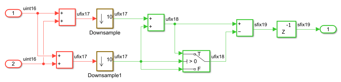
The color-coded regions indicate the two sample rates in the model:
Red region: Runs at the base rate, which is the fastest rate in the model.
Green region: Runs at a rate that is ten times slower than the base rate.
To generate the multicycle path constraints, open theConfiguration Parameters dialog box. In the HDL Code Generation > Optimization > General pane, select Enable-based Constraints. Alternatively, use the hdlset_param command:
hdlset_param("DualRatesNoOffset","MulticyclePathConstraints","on");
Generate the HDL code for the DUT subsystem.
makehdl("DualRatesNoOffset/DUT");### Working on the model DualRatesNoOffset ### Generating HDL for DualRatesNoOffset/DUT ### Using the config set for model DualRatesNoOffset for HDL code generation parameters. ### Running HDL checks on the model 'DualRatesNoOffset'. ### Begin compilation of the model 'DualRatesNoOffset'... ### Working on the model 'DualRatesNoOffset'... ### Working on... GenerateModel ### Begin model generation 'gm_DualRatesNoOffset'... ### Copying DUT to the generated model.... ### Model generation complete. ### Generated model saved at hdlsrc\DualRatesNoOffset\gm_DualRatesNoOffset.slx ### Begin VHDL Code Generation for 'DualRatesNoOffset'. ### Begin VHDL Code Generation for 'DUT_tc'. ### Working on DUT_tc as hdlsrc\DualRatesNoOffset\DUT_tc.vhd. ### Code Generation for 'DUT_tc' completed. ### Working on DualRatesNoOffset/DUT as hdlsrc\DualRatesNoOffset\DUT.vhd. ### Code Generation for 'DualRatesNoOffset' completed. ### Generating HTML files for code generation report at index.html ### Writing Vivado multicycle constraints XDC file hdlsrc\DualRatesNoOffset\DUT_constraints.xdc ### Creating HDL Code Generation Check Report DUT_report.html ### HDL check for 'DualRatesNoOffset' complete with 0 errors, 0 warnings, and 0 messages. ### HDL code generation complete.
In a multirate design, HDL Coder generates timing controller logic that manages clock-enable signals for slower rates. The timing controller produces clock-enable signals for each rate and phase. This code snippet shows the enable signals for each rate and phase in DUT_tc.vhd.
-- Master clock enable input: clk_enable
--
-- enb_1_10_0  : 10x slower than clk with last phase
-- enb_1_10_1  : 10x slower than clk with phase 1
...
...
ENTITY DUT_tc IS
  PORT( clk                               :   IN    std_logic;
        reset                             :   IN    std_logic;
        clk_enable                        :   IN    std_logic;
        enb_1_10_0                        :   OUT   std_logic;
        enb_1_10_1                        :   OUT   std_logic
        );
END DUT_tc;

...
...

  ATTRIBUTE keep : boolean;
  ATTRIBUTE mcp_info : string;
  ATTRIBUTE direct_enable : string;

  ATTRIBUTE keep OF phase_0 : SIGNAL IS true;
  ATTRIBUTE mcp_info OF phase_0 : SIGNAL IS "DUT_tc.u1_d10_o0";
  ATTRIBUTE keep OF phase_1 : SIGNAL IS true;
  ATTRIBUTE mcp_info OF phase_1 : SIGNAL IS "DUT_tc.u1_d10_o1";
  ATTRIBUTE direct_enable OF enb_1_10_0 : SIGNAL IS "yes";
  ATTRIBUTE direct_enable OF enb_1_10_1 : SIGNAL IS "yes";
...
...
These enable signals control registers in different rate regions and ensure they execute on the correct cycles. HDL Coder uses these signals to identify multicycle paths and generate MCP constraints for synthesis tools. It also applies synthesis attributes such as direct_enable, keep, and mcp_info to the enable signals and phase registers to preserve them. HDL Coder creates an XDC file named DUT_constraints.xdc for the DUT subsystem to relax timing requirements on multicycle paths. This code snippet shows the MCP constraints generated for slower rates and phases.
type hdlsrc\DualRatesNoOffset\DUT_constraints.xdc# Multicycle constraints for clock enable: DUT_tc.u1_d10_o0
set enbregcell [get_cells -hier -filter {mcp_info=="DUT_tc.u1_d10_o0"}]
set enbregnet [get_nets -of_objects [get_pins -of_objects $enbregcell -filter {DIRECTION == OUT}]]
set reglist1 [get_cells -of [filter [all_fanout -flat -endpoints_only $enbregnet] IS_ENABLE]]
set_multicycle_path 10 -setup -from $reglist1 -to $reglist1 -quiet
set_multicycle_path 9 -hold -from $reglist1 -to $reglist1 -quiet
# Multicycle constraints for clock enable: DUT_tc.u1_d10_o1
set enbregcell [get_cells -hier -filter {mcp_info=="DUT_tc.u1_d10_o1"}]
set enbregnet [get_nets -of_objects [get_pins -of_objects $enbregcell -filter {DIRECTION == OUT}]]
set reglist2 [get_cells -of [filter [all_fanout -flat -endpoints_only $enbregnet] IS_ENABLE]]
set_multicycle_path 10 -setup -from $reglist2 -to $reglist2 -quiet
set_multicycle_path 9 -hold -from $reglist2 -to $reglist2 -quiet
# Multicycle constraints from clock enable: DUT_tc.u1_d10_o1 to clock enable: DUT_tc.u1_d10_o0
set_multicycle_path 9 -setup -from $reglist2 -to $reglist1 -quiet
set_multicycle_path 8 -hold -from $reglist2 -to $reglist1 -quiet
The MCP constraints ensure that the destination register has multiple clock cycles and meets the setup timing requirements while maintaining a safe hold check one cycle earlier. In the slower clock domain, the intra-phase paths use setup and hold multipliers of 10 and 9, respectively, while the cross-phase paths that have a one-phase difference use setup and hold multipliers of 9 and 8.
Supported Synthesis Tools for Multicycle Path Constraints
Enable-based multicycle path constraints have various file formats that depend on the synthesis tool that you specify. This table lists the synthesis tools that HDL Coder supports for enable‑based multicycle path constraints and shows representative constraint snippets for each tool.
| Synthesis Tool | Constraint File Format | Generated MCP Constraints |
|---|---|---|
Altera® Quartus® II | SDC |
# Multicycle constraints for clock enable: DUT_tc.u1_d4_o0 set enbreg [get_registers *u_DUT_tc|phase_0] set_multicycle_path 4 -to [get_fanouts $enbreg -through [get_pins -hier *|ena]] -end -setup set_multicycle_path 3 -to [get_fanouts $enbreg -through [get_pins -hier *|ena]] -end -hold |
Cadence® Genus | SDC |
# Multicycle constraints for clock enable: MCP_Subsystem_tc.u1_d5_o0 set MCPnet0 [get_db hnets .name *u_MCP_Subsystem_tc/phase_0] set MCPreg0 [get_cells -of [all_fanout -flat -endpoints_only -from $MCPnet0]] set_multicycle_path 5 -setup -from $MCPreg0 -to $MCPreg0 set_multicycle_path 4 -hold -from $MCPreg0 -to $MCPreg0 |
Xilinx® Vivado® | XDC |
# Multicycle constraints for clock enable: DUT_tc.u1_d4_o0
set enbregcell [get_cells -hier -filter {mcp_info=="DUT_tc.u1_d4_o0"}]
set enbregnet [get_nets -of_objects [get_pins -of_objects $enbregcell -filter {DIRECTION == OUT}]]
set reglist [get_cells -of [filter [all_fanout -flat -endpoints_only $enbregnet] IS_ENABLE]]
set_multicycle_path 4 -setup -from $reglist -to $reglist -quiet
set_multicycle_path 3 -hold -from $reglist -to $reglist -quiet |
Xilinx ISE | UCF |
# Multicycle constraints for clock enable: DUT_tc.u1_d4_o0
NET "*u_DUT_tc/phase_0" TNM_NET = FFS "TN_u_DUT_tc_phase_0";
TIMESPEC "TS_u_DUT_tc_phase_0" = FROM "TN_u_DUT_tc_phase_0" TO "TN_u_DUT_tc_phase_0" TS_FPGA_CLK/4;
This code shows the clock constraints that HDL
Coder generates when you set the Target
Workflow parameter in the HDL Workflow
Advisor to # Timing Specification Constraints NET "clk" TNM_NET = "TN_clk"; TIMESPEC "TS_FPGA_CLK" = PERIOD "TN_clk" 300 MHz; To use the multicycle path
constraints when you generate HDL code by using the
|
You can use the enable-based multicycle constraints when you set the Target workflow parameter in the HDL Workflow Advisor to these settings:
Generic ASIC/FPGAIP Core GenerationSimulink Real-Time FPGA I/O.
The multicycle path constraints file is not supported with when you set the
Target Workflow parameter in the HDL Workflow Advisor to
FPGA-in-the-Loop.
HDL Coder uses different synthesis constructs and attributes when generating multicycle path constraints. For more information, see Attributes and MCP Constructs Used in Enable-Based Constraints.
Choose Between Multicycle Path Constraints or Clock Rate Pipelining
You can choose whether to meet timing requirements by relaxing register‑to‑register timing by using multicycle path constraints or by inserting pipelines by using clock-rate pipelining (CRP). Both approaches help you achieve timing requirements for FPGA and ASIC targets.
Use MCP when:
You want to minimize area and power and keep the original HDL architecture.
Your design is multi-rate under a single clock with enable-gated slower clock domains.
You want to preserve original architecture and disable pipeline-adding optimizations.
Your synthesis tool supports enable-based multicycle constraints.
Use CRP when:
You need maximum clock frequency or higher throughput.
You plan to use distributed or adaptive pipelining, resource sharing, or streaming.
You use DSP and RAM mapping, which can improve synthesis results.
You want robustness across synthesis tool flows without relying on constraint files.
For more information on the usage of MCP and CRP, see Choose Between Multicycle Path Constraints and Clock-Rate Pipelining.
Limitations
If you do not bound the slow-rate region by using registers, you must add two Delay blocks at the slow rate, which increases the latency of your design.
The code generator does not add constraints on paths between registers that have a nonzero phase value for the timing controller-based enable signals. For the code generator to add constraints, use registers that derive from phase
0clock enable signals, such as Delay blocks.The generated multicycle constraints can be less effective if you apply the constraints to regions that have optimizations such as clock-rate pipelining and adaptive pipelining enabled. With clock-rate pipelining, the registers operate at the faster clock rate and might not retain the slow-rate registers in your design.
HDL Coder does not generate multicycle path constraints for single-rate models.
If you use the multiple clock mode, the code generator does not output the multicycle path constraints file.
Multicycle path constraints is not supported for synthesis tools such as Microchip Libero® SoC and Intel® Quartus Prime.