Use IP Core Generation to Access DUT Registers on Pure AMD FPGA Devices
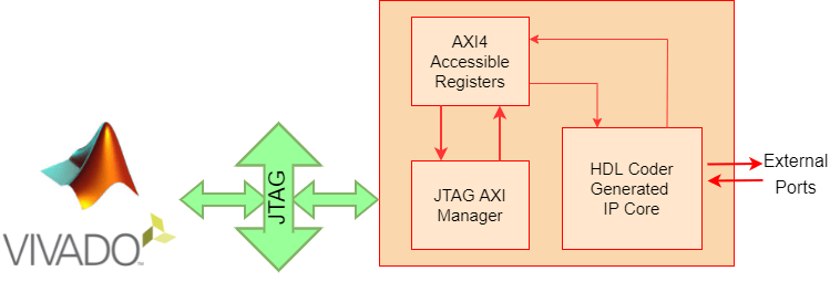
This example shows how to use the HDL Coder™ IP core generation workflow to develop reference designs for Xilinx® parts that do not use an embedded ARM® processor present but that still utilize the HDL Coder generated AXI interface to control the design under test (DUT). This example uses the HDL Verifier™ AXI Manager IP to access the HDL Coder generated DUT registers from MATLAB®. Alternatively, you can use the Xilinx JTAG AXI Master to access the DUT registers using Vivado® Tcl console by writing Tcl commands. For the Xilinx JTAG AXI Master, you must create a custom reference design. The FPGA design is implemented on the Xilinx Kintex®-7 KC705 board.
Requirements
Xilinx Vivado Design Suite, with a supported version listed in HDL Language Support and Supported Third-Party Tools and Hardware
Xilinx Kintex-7 KC705 development board
HDL Coder Support Package for AMD FPGA and SoC Devices
HDL Verifier™ Support Package for AMD® FPGA and SoC Devices
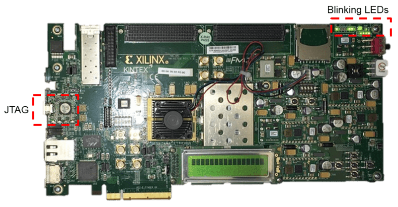
Xilinx Kintex-7 KC705 Development Board
This figure shows the Xilinx Kintex-7 KC705 development board.
Example Reference Designs
Designs that can benefit from using the HDL Coder IP core generation workflow without using either an embedded ARM processor or an Embedded Coder™ support package but still leverage the HDL Coder generated AXI4-Lite registers can include one of these IP sets.
HDL Verifier AXI Manager + HDL Coder IP Core
Xilinx JTAG Master + HDL Coder IP Core
MicroBlaze™ + HDL Coder IP Core
PCIe Endpoint + HDL Coder IP Core
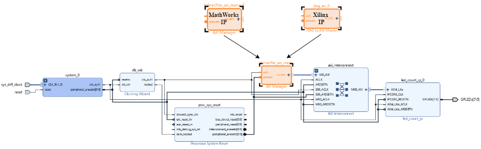
This example includes two reference designs.
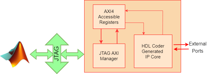
The Default System reference design uses MathWorks® IP and a MATLAB command line interface for issuing read and write commands. To use this design, you must have the HDL Verifier product.
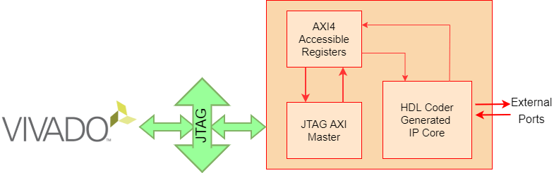
The Xilinx JTAG to AXI Master reference design uses Vivado IP for the JTAG to AXI Master and requires using the Vivado Tcl console to issue read and write commands.
The two reference designs differ by only the JTAG manager IP that they use, as this figure shows.
HDL Verifier AXI Manager Reference Design
In the IP core generation workflow of the HDL Workflow Advisor, in the Set Target Reference Design step, set the Insert AXI Manager (HDL Verifier required) parameter to an interface that communicates between your host machine and the target hardware. This option adds AXI manager IP for your interface automatically into the reference design and connects the added IP to the DUT IP's register interface using AXI4-Lite or AXI4 protocol. The next section details the steps to auto-insert the JTAG AXI Manager IP in the reference design.
Execute IP Core Workflow
Follow these steps to execute the IP core workflow for the Default System reference design, which uses JTAG AXI Manager IP. Using this reference design, you can generate an HDL IP core that blinks LEDs on the KC705 board. To generate an HDL IP core, follow these steps.
1. Set up the Xilinx Vivado tool path by executing hdlsetuptoolpath command in MATLAB. Use your own Xilinx Vivado installation path when executing the command.
hdlsetuptoolpath('ToolName','Xilinx Vivado','ToolPath', ...
                 vivadopath);
2. Open the Simulink model that implements LED blinking by executing this command in MATLAB.
open_system('hdlcoder_led_blinking')
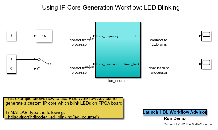
3. To launch the HDL Workflow Advisor, Select the hdlcoder_led_blinking/led_counter subsystem. In the Simulink Toolstrip, on the Apps tab, select HDL Coder. Then, on the HDL Code tab, in the Assistance section, click Workflow Advisor.
4. In step 1.1, set Target workflow to IP Core Generation and Target platform to Xilinx Kintex-7 KC705 development board. Click Run This Task.
5. In step 1.2, set Reference design to Default System. Under Reference design parameters, set Insert AXI Manager (HDL Verifier required) to JTAG. Click Run This Task.
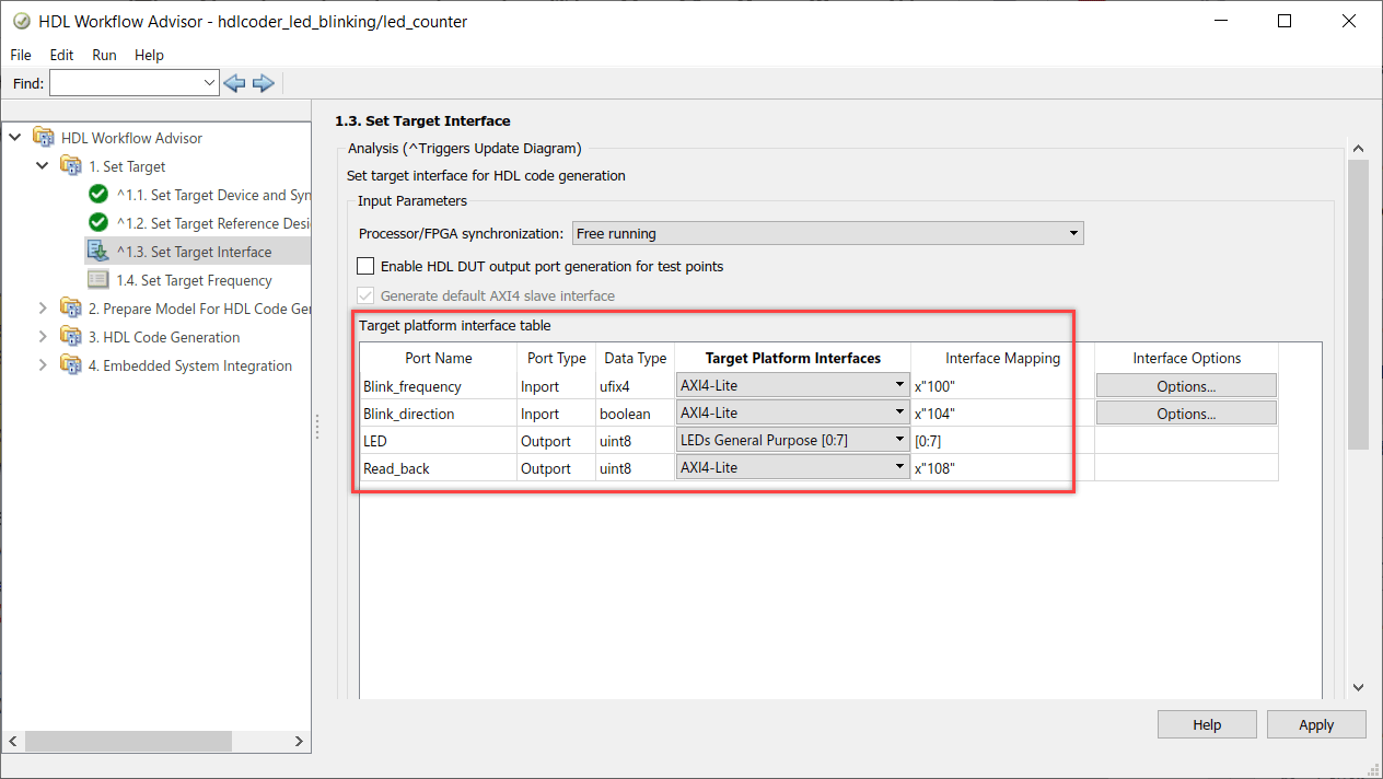
6. In step 1.3, set the interface of the Blink_frequency, Blink_direction, and Read_back ports to AXI4-Lite. Set the interface of the LED port to LEDs General Purpose [0:7].
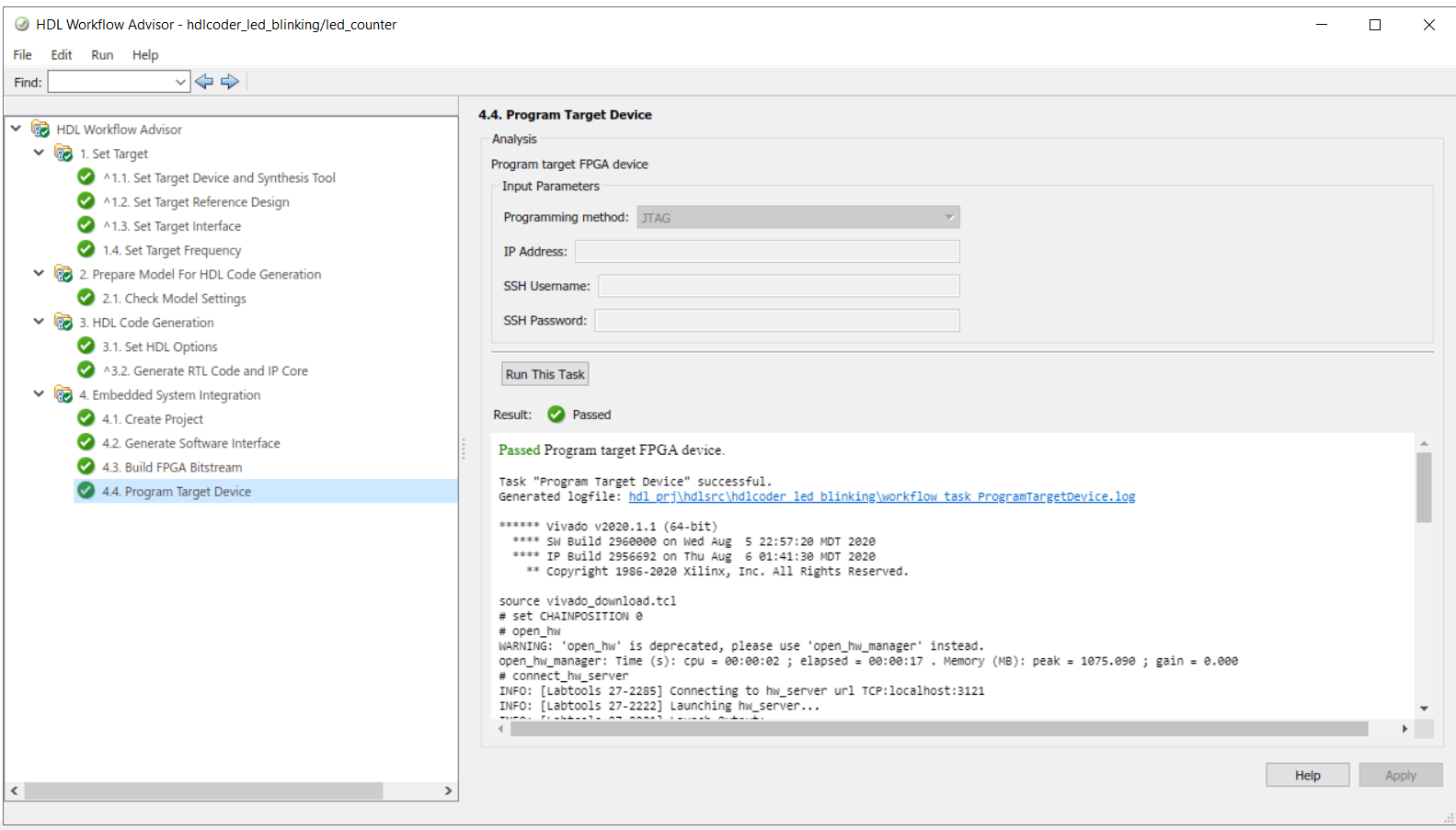
7. Run the remaining steps in the workflow to generate a bitstream and program the target device.
Unlike the Zynq-based reference design, a Generate Software Interface Model task does not exist, as this figure shows.
Determine Addresses from IP Core Report
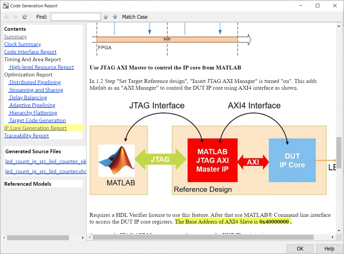
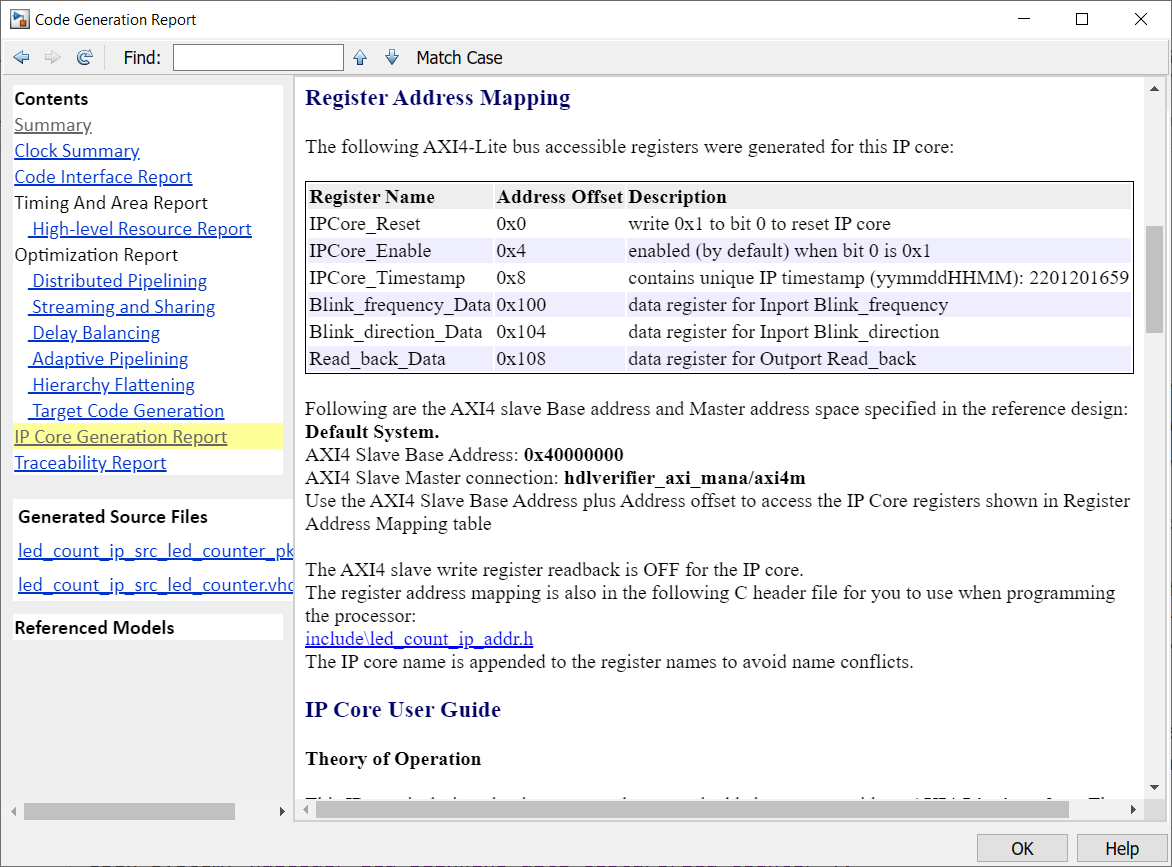
The base address for an HDL Coder IP core is defined as 0x40000000 for the Default System reference design, which uses the AXI Manager IP. You can see address setting in the generated IP core report as shown in this figure.
The IP core report register address mapping table shows the offsets.
HDL Verifier Command Line Interface
If you have the HDL Verifier™ Support Package for AMD® FPGA and SoC Devices, select the AXI Manager reference design, then you can use MATLAB command line interface to access the IP core that is generated by the HDL Coder product.
To write and read from the DDR memory, follow these steps.
1. Create an AXI manager object.
h = aximanager('Xilinx')
2. Issue a write command. For example, disable the DUT.
h.writememory('40000004',0)
3. Re-enable the DUT.
h.writememory('40000004',1)
4. Issue a read command. For example, read the current counter value.
h.readmemory('40000108',1)
5. Delete the object to free up the JTAG resource. If you do not delete the object, other JTAG operations, such as programming the FPGA, fail.
delete(h)
Xilinx JTAG to AXI Master Reference Design
Create a custom reference design to use the Xilinx JTAG to AXI Master IP in the reference design, and then add the reference design files to the MATLAB path using the addpath command.
Access the HDL Coder IP core registers using the Xilinx JTAG to AXI Master IP by using the base address that is defined in reference design plugin file.
Vivado Tcl Commands for AXI Read and Write
This example uses the standalone Vivado Tcl console for basic commands to issue reads and writes. You can use these commands to open the JTAG device and set up an "enable" and "disable" write to the DUT. Once the Xilinx JTAG to AXI Master IP got inserted into the design, you can enter these commands directly into the Vivado Tcl console or save them in a Tcl file and source them later. For simplicity, copy these Tcl commands into a file open_jtag.tcl.
# Open connection to the JTAG Master
open_hw_manager
connect_hw_server
open_hw_target
refresh_hw_device [lindex [get_hw_devices] 0]
# Create some reads/writes
create_hw_axi_txn wr_enable [get_hw_axis hw_axi_1] -address 44a0_0004 -data 0000_0001 -type write
create_hw_axi_txn wr_disable [get_hw_axis hw_axi_1] -address 44a0_0004 -data 0000_0000 -type write
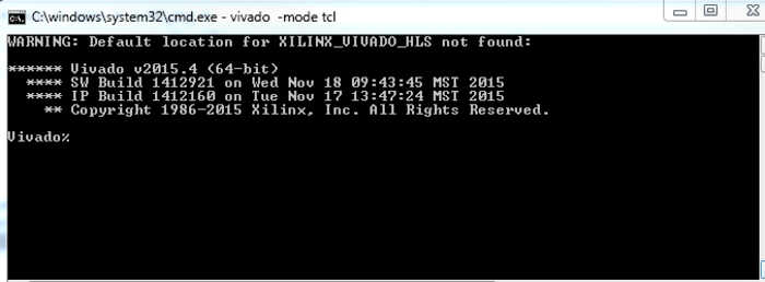
Launch the Vivado Tcl console, sourcing the file you just created.
system('vivado -mode tcl -source open_jtag.tcl&')
When you are done using the JTAG Master, close the connection by using these Tcl commands.
# Close and disconnect from the JTAG Master
close_hw_target;
disconnect_hw_server;
Summary
You can use the JTAG AXI Manager IP to interface with HDL Coder IP core registers in systems that do not have an embedded ARM processor, such as the Kintex-7. You can use this IP as a first step to debug standalone HDL Coder IP cores, prior to hand coding software for soft processors, (such as MicroBlaze), or as a way to tune parameters on a running system.