Pressure-Reducing Valve (IL)
Pressure-reducing valve in an isothermal liquid network

Libraries:
Simscape /
Fluids /
Isothermal Liquid /
Valves & Orifices /
Pressure Control Valves
Description
The Pressure-Reducing Valve (IL) block represents a pressure-reducing valve in an isothermal liquid network. The valve remains open when the pressure at port B is less than a specified pressure. When the pressure at port B meets or surpasses this pressure, the valve closes. The block operates based on the differential between the set pressure and the pressure at port B. The block contains a check valve portion that functions identically to the Check Valve (IL) block during flow reversals. For pressure control based on another location in the fluid network, see the Pressure Compensator Valve (IL) block.
Set Pressure Control
The block regulates pressure between the set pressure and maximum pressure. When you set Set pressure control to:
Controlled— You can connect a pressure signal to port Ps. The block regulates pressure when the pressure at port B is greater than the reference set pressure, Pset, and below Pmax. The pressure at port B acts as the control pressure, Pcontrol, for this valve.Pmax is the sum of Pset and the pressure regulation range.
Constant— The Set pressure (gauge) parameter defines a constant set pressure.
How the block determines the pressure regulation range depends on the Opening parameterization parameter:
Linear - Area vs. pressure— The Pressure regulation range parameter defines the pressure regulation range.Tabulated data - Area vs. Pressure— The pressure regulation range is the difference between the last and first elements of the Pressure at port B (gauge) vector parameter.Tabulated data - Volumetric flow rate vs. pressure— The pressure regulation range is the difference between the first and last elements of the Reference pressure at port B (gauge) vector parameter.
Area vs. Pressure Parameterizations
When you set Opening parameterization to Linear - Area
vs. pressure, the block calculates the valve area as
where the normalized pressure,, is
When the valve is in a near-open or near-closed position in the linear parameterization, you can maintain numerical robustness in your simulation by adjusting the Smoothing factor parameter. If the Smoothing factor parameter is nonzero, the block smoothly saturates the control pressure between pset and pmax. For more information, see Numerical Smoothing.
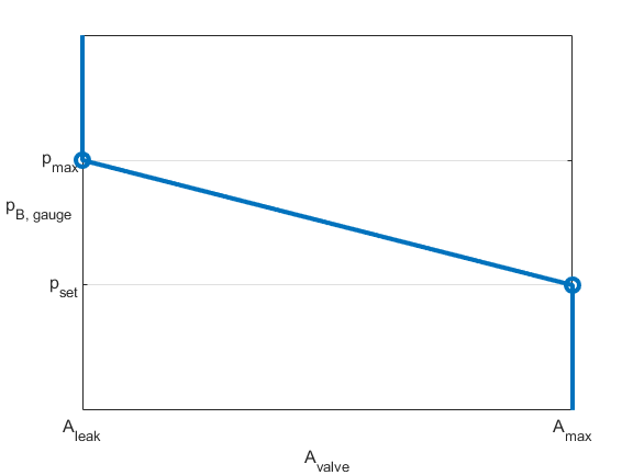
The figure demonstrates the opening characteristics of the valve when using the linear area parameterization. The opening area, Avalve, drops linearly with the outlet pressure, pB,gauge. The opening area ranges from Aleak to AMax, and the pressure operating range starts at pset and goes to pmax.
When you set Opening parameterization to Tabulated data -
Area vs. Pressure, the block calculates the opening area as
where:
pcontrol = pB,gauge is the control pressure.
pcontrol,TLU = pB,TLU + poffset.
pB,TLU is the Pressure at port B (gauge) vector parameter.
poffset is an internal pressure offset that causes the valve to start closing when pB,Gauge = pset, where poffset = pset - pB,TLU(1).
ATLU is the Opening area vector parameter.
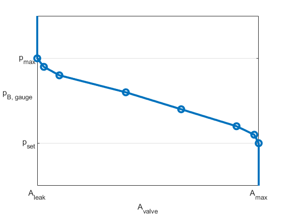
Amax and Aleak are the first and last parameters of the Opening area vector parameter, respectively. The figure demonstrates the opening characteristics of the valve when using the tabulated area parameterization.
When you set Opening parameterization to
Linear - Area vs. pressure or
Tabulated data - Area vs. Pressure, the block
conserves mass such that:
The block calculates the mass flow rate as
where:
Cd is the Discharge coefficient parameter.
Avalve is the instantaneous valve open area.
Aport is the Cross-sectional area at ports A and B parameter.
is the average fluid density.
Δp is the valve pressure difference pA – pB.
The critical pressure difference, Δpcrit, is the pressure differential associated with the Critical Reynolds number parameter, Recrit, the flow regime transition point between laminar and turbulent flow:
Pressure loss describes the reduction of pressure in the valve due to a decrease in area. The block calculates PRloss as:
Pressure recovery describes the positive pressure change in the valve due to an increase in area. If you do not want to capture this increase in pressure, clear the Pressure recovery check box. In this case, PRloss is 1.
The block determines the opening area, Avalve, using the valve opening dynamics.
When you select Opening dynamics, the block applies a first-order filter to the valve area based on the Opening time constant parameter, τ. The valve area, Avalve, becomes the dynamic area, Adyn,
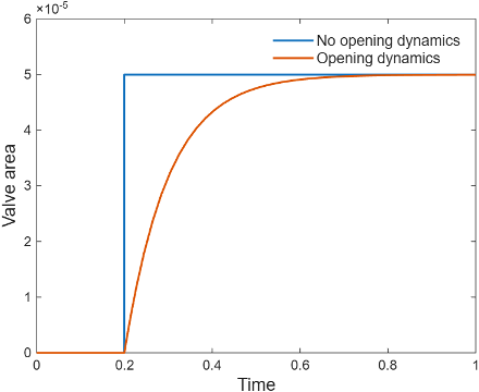
When you select Opening dynamics, the valve does not respond to changes instantaneously. This figure shows an example valve area in response to a step in the valve input pressure with and without opening dynamics:
When you clear Opening dynamics, the valve area mirrors the step change in the pressure at the input.
When you select Opening dynamics and set Opening time constant to
0.1 s, the valve area asymptotically approaches its limit.
Specifying a nonzero value for the Smoothing factor parameter provides additional numerical stability when the valve area is changing and in the near-closed or near-open position. For more information, see Numerical Smoothing.
The block calculates the steady-state dynamics based on the control pressure, pcontrol, and using the same parameterization as the valve opening.
Volumetric Flow Rate vs. Pressure Parameterization
The volumetric flow rate parameterization equations refer to these quantities:
⩒TLU,ref is the Reference volumetric flow rate vector parameter.
PA,gauge,ref and PB,gauge,ref are the Reference pressure at port A (gauge) vector and Reference pressure at port B (gauge) vector parameters, respectively.
pset,gauge is either the Set pressure (gauge) parameter or the signal at port Ps.
K is the flow coefficient through the reducing stage, which the block calculates during the simulation.
is the average fluid density in the reducing valve.
Δp is the pressure drop across the valve for fluid flow.
Δpcrit is the critical pressure drop for fluid flow.
Cd is the discharge coefficient, which the block sets internally for the volumetric flow rate parameterization.
Recrit is the critical Reynolds number, which the block sets internally.
ν is the kinematic viscosity, which is constant for the isothermal liquid network.
When you set Opening parameterization to
Tabulated data - Volumetric flow rate vs. pressure,
the block calculates the smoothed mass flow rate of the reducing valve such that
where the block computes K using a
tablelookup function such that
The block calculates the control pressure as
where the block sets the drain pressure, pdrain, to 1 atm. The block calculates the reference control pressure vector as
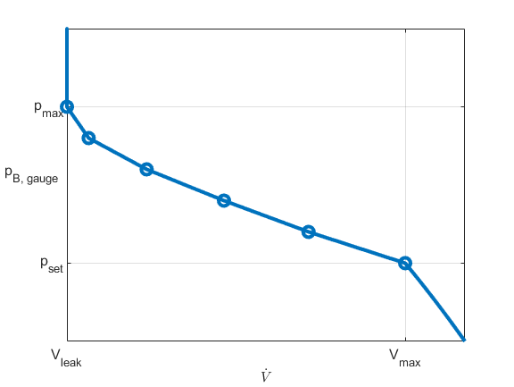
where poffset is an internally computed pressure offset that causes the valve to start shutting when pB,gauge,ref = pset,gauge. Thus, poffset = pset,gauge - pB,gauge,ref. The figure shows how the block controls pressure using the tabulated volumetric flow rate parameterization.
Faults
To model a fault, in the Faults section, click the Add fault hyperlink next to the fault that you want to model. Use the fault parameters to specify the fault properties. For more information about fault modeling, see Introduction to Simscape Faults.
Three fault options are available for the reducing valve and check valve. For the Reducing valve opening when faulted and Check valve opening when faulted parameters, you can choose:
Closed— The valve shuts to its smallest opening value, depending on the Opening parameterization parameter. When you set Opening parameterization to:Linear - Area vs. pressure— The valve area reduces to the value of the Leakage area parameter.Tabulated data - Area vs. pressure— The valve area reduces to the value of the last element in the Opening area vector parameter.Tabulated data - Volumetric flow rate vs. pressure— The flow coefficient reduces to the value of the last element of the derived flow coefficient lookup table, KTLU,Ref.
Open— The valve opens to its largest opening value, depending on the Opening parameterization parameter. When you set Opening parameterization to:Linear - Area vs. pressure— The valve area opens to the value of the Maximum opening area.Tabulated data - Area vs. pressure— The valve area opens to the value of the first element in the Opening area vector.Tabulated data - Volumetric flow rate vs. pressure— The flow coefficient reduces to the value of the first element of the derived flow coefficient lookup table, KTLU,Ref.
Maintain last value— The valve area remains at the valve opening area when the trigger occurred.
For the linear parameterization, numerical smoothing at the extremes of the valve area causes the minimum area applied to be larger than the Leakage area parameter, and the maximum is smaller than the Maximum orifice area parameter.
After the fault triggers, the valve remains at the faulted area for the rest of the simulation.