Pressure Relief Valve (IL)
Pressure-relief valve in an isothermal liquid network

Libraries:
Simscape /
Fluids /
Isothermal Liquid /
Valves & Orifices /
Pressure Control Valves
Description
The Pressure Relief Valve (IL) block represents a pressure relief valve in an isothermal liquid network. The valve remains closed when the pressure is less than a specified value. When this pressure is met or surpassed, the valve opens. This set pressure is either a threshold pressure differential over the valve, between ports A and B, or between port A and atmospheric pressure. For pressure control based on another element in the fluid system, see the Pressure Compensator Valve (IL) block.
Pressure Control
For linear preparameterizations, the normalized pressure, , which controls the valve opening area, depends on the value of the Set pressure control parameter.
When you set Set pressure control to
Constant and Opening
parameterization to Linear - Area vs.
pressure, the normalized pressure is
where:
pcontrol is the control pressure. When you set Opening pressure specification to
Pressure differential, the control pressure is pA ̶ pB. When you set Opening pressure specification toPressure at port A, the control pressure is the difference between the pressure at port A and atmospheric pressure.pset is the set pressure. When Opening pressure specification is
Pressure differential, pset is the value of the Set pressure differential parameter. When Opening pressure specification isPressure at port A, pset is the value of the Set pressure (gauge) parameter.pmax is the maximum of pressure regulation range, pmax = pset + prange, where prange is the value of the Pressure regulation range parameter.
When you set Set pressure control to
Controlled, the normalized pressure is
where:
ps is the value of the signal at port Ps.
pmax = ps + prange, where prange is the value of the Pressure regulation range parameter.
pcontrol is the pressure differential between ports A and B, pA ̶ pB.
Opening Parameterization
The mass flow rate depends on the values of the Set pressure control and Opening parameterization parameters.
When you set Set pressure control to
Controlled, or to
Constant and Opening
parameterization to Linear - Area vs.
pressure or Tabulated data - Area vs.
pressure, the mass flow rate is
where:
Cd is the value of the Discharge coefficient.
Avalve is the instantaneous valve open area.
Aport is the value of the Cross-sectional area at ports A and B.
is the average fluid density.
Δp is the valve pressure difference pA – pB.
The critical pressure difference, Δpcrit, is the pressure differential associated with the Critical Reynolds number, Recrit, the flow regime transition point between laminar and turbulent flow:
Pressure loss describes the reduction of pressure in the valve due to a decrease in area. PRloss is calculated as:
Pressure recovery is the positive pressure change in the valve due to an increase in area. If you do not want to capture this increase in pressure, clear the Pressure recovery check box. In this case, PRloss is 1.
When you set Set pressure control to
Controlled, or to
Constant and Opening
parameterization to Linear - Area vs.
pressure, the opening area is
where:
Aleak is the value of the Leakage area parameter.
Amax is the value of the Maximum opening area parameter.
When the valve is in a near-open or near-closed position in the linear parameterization, you can maintain numerical robustness in your simulation by adjusting the Smoothing factor parameter. If the Smoothing factor parameter is nonzero, the block smoothly saturates the control pressure between pset and pmax. For more information, see Numerical Smoothing.
When you set Set pressure control to
Constant and Opening
parameterization to Tabulated data - Area vs.
pressure, the block interpolates
Avalve from the
Opening area vector parameter with respect to the
Pressure differential vector or Opening
pressure (gauge) vector parameter, depending on the value of the
Pressure control specification parameter. The block
also uses the smoothed, normalized pressure when the smoothing factor is nonzero
with linear interpolation and nearest extrapolation.
When you set Set pressure control to
Constant and Opening
parameterization to Tabulated data - Volumetric flow
rate vs. pressure, the valve opens according to the
user-provided tabulated data of volumetric flow rate and pressure differential
between ports A and B.
The mass flow rate is
where:
is the average fluid density.
where Cd is the discharge coefficient, Recrit is the critical Reynolds number, and ν is the kinematic viscosity. In this parameterization, Cd and Recrit are fixed at
0.64and150, respectively.
When the block operates in the limits of the tabulated data,
where:
ΔpTLU is the Pressure drop vector parameter.
where TLU is the Volumetric flow rate vector parameter.
When the simulation pressure falls below the first element of the Pressure drop
vector parameter,
K=KLeak,
where TLU(1) is the first element of the Volumetric flow rate vector parameter.
When the simulation pressure rises above the last element of the Pressure drop
vector parameter,
K=KMax,
where TLU(end) is the last element of the Volumetric flow rate vector parameter.
Conservation of Mass
The block conserves mass through the valve such that
where is the mass flow rate into the valve through the port indicated by the A or B subscript.
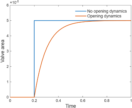
Opening Dynamics
When you select Opening dynamics, the block applies a first-order filter to the valve area based on the Opening time constant parameter, τ. The valve area, Avalve, becomes the dynamic area, Adyn,
When you select Opening dynamics, the valve does not respond to changes instantaneously. This figure shows an example valve area in response to a step in the valve input pressure with and without opening dynamics:
When you clear Opening dynamics, the valve area mirrors the step change in the pressure at the input.
When you select Opening dynamics and set Opening time constant to
0.1 s, the valve area asymptotically approaches its limit.
Specifying a nonzero value for the Smoothing factor parameter provides additional numerical stability when the valve area is changing and in the near-closed or near-open position. For more information, see Numerical Smoothing.
Faults
To model a fault, in the Faults section, click the Add fault hyperlink next to the fault that you want to model. Use the fault parameters to specify the fault properties. For more information about fault modeling, see Introduction to Simscape Faults.
The Opening area when faulted parameter has three fault options:
Closed— The valve freezes at its smallest value, depending on the Opening parameterization parameter:When you set Opening parameterization to
Linear - Area vs.
					pressure
, the valve area freezes at the Leakage area parameter.When you set Opening parameterization to
Tabulated data - Area vs. pressure, the valve area freezes at the first element of the Opening area vector parameter.
Open— The valve freezes at its largest value, depending on the Opening parameterization parameter:When you set Opening parameterization to
Linear - Area vs. pressure, the valve area freezes at the Maximum opening area parameter.When you set Orifice parameterization to
Tabulated data - Area vs.
						pressure
, the valve area freezes at the last element of the Opening area vector parameter.
Maintain last value— The valve area freezes at the valve open area when the trigger occurred.
Due to numerical smoothing at the extremes of the valve area, the minimum area the block uses is larger than the Leakage area parameter, and the maximum is smaller than the Maximum orifice area parameter, in proportion to the Smoothing factor parameter value.
After the fault triggers, the valve remains at the faulted area for the rest of the simulation.
When you set Opening parameterization to
Tabulated data - Volumetric flow
						rate vs. pressure
,
the fault options are defined by the volumetric flow rate through the valve:
Closed— The valve stops at the mass flow rate associated with the first elements of the Volumetric flow rate vector parameter and the Pressure drop vector parameter:Open— The valve stops at the mass flow rate associated with the last elements of the Volumetric flow rate vector parameter and the Pressure drop vector parameter:Maintain at last value— The valve stops at the mass flow rate and pressure differential when the trigger occurs:
where
Generate Derived Data Sheet
Since R2026a
You can generate a derived data sheet for the Pressure Relief Valve (IL) block. Derived data sheets use built-in MATLAB live scripts to provide information about the block parameterization. The script imports the parameters from the selected Pressure Relief Valve (IL) block and uses the parameters to generate characteristic plots. You can use the derived data sheet to investigate block behavior, check block parameterizations, or share component-level design. To generate the derived data sheet:
Double-click the Pressure Relief Valve (IL) block.
In the block dialog box, click the Open live script button next to Derived data sheet.
In the live script, click the Generate data sheet button.
The derived data sheet includes performance curves for pressure verses volumetric flow rate for the selected block.
Examples

Priority Valve Controlling Two Hydraulic Motors
A pressure-compensated 3-way flow control valve. This valve maintains constant flow rate through the main hydraulic motor, which is connected to the pressure-compensated outlet of the flow control valve. It acts as a priority valve, diverting the excess flow to the auxiliary hydraulic motor if the main hydraulic motor receives enough fluid to maintain a preset angular velocity. The auxiliary motor is shut off completely if there is insufficient flow to power the main hydraulic motor.
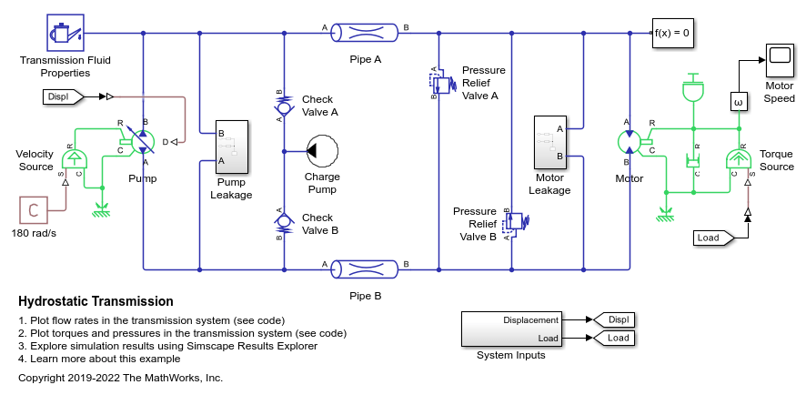
Hydrostatic Transmission
A hydraulic transmission system built of a variable-displacement pump and a fixed-displacement motor. The pipes between the pump and the motor are connected by two replenishing valves (check valves) and a charge pump on the pump side and two pressure relief valves on the motor side. The motor drives a mechanical load consisting of an inertia, viscous friction, and time-varying torque. The system is tested with both positive and negative pump flow rate by varying the pump displacement.