Main Content

Lidar Sensor

Generate lidar point cloud data for a scene

Since R2023a

  • Lidar Sensor block

Libraries:
Lidar Toolbox

Description

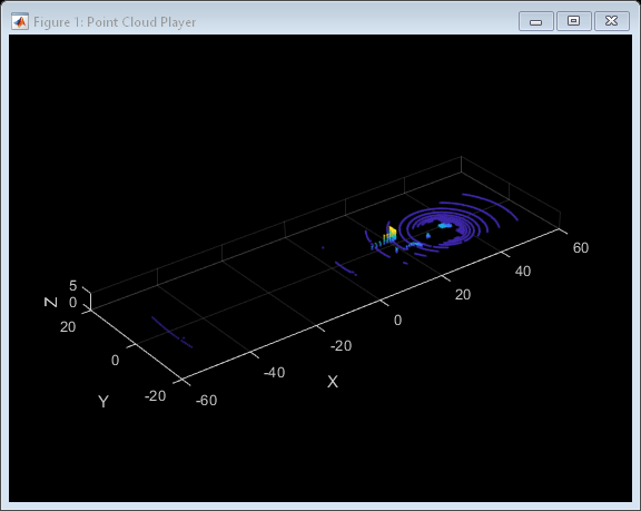
The Lidar Sensor block generates point cloud data from the measurements recorded by a lidar sensor mounted on an ego vehicle. The generated data is in the ego vehicle coordinate system.

To generate point cloud data for a scene, you can configure the sensor and actor poses by using this block. The block also outputs the intensity and segmentation values for the generated points.

Additionally, you can use this block to

  • configure the lidar sensor parameters such as range, azimuth angles, and elevation angles.

  • add random Gaussian noise to the points in the point cloud.

  • simulate weather conditions such as fog and rain.

You can use the drivingScenario (Automated Driving Toolbox) object to create a scenario containing actors and trajectories, import this data into Simulink® by using the Scenario Reader (Automated Driving Toolbox) block and then generate the point cloud data for the scenario by using the Lidar Sensor block.

You can also use the block with vehicle actors in RoadRunner Scenario simulations. The block does not require any inputs when used with actors in a RoadRunner Scenario simulation. For more information, see Integrate Lidar Sensor Model into RoadRunner Scenario and Cosimulate with Unreal Engine. (since R2024a)

Ports

Input

expand all

Actor poses, specified as a Simulink bus containing MATLAB structure. The structure must contain these two fields.

  1. Target poses of the actors in the scene, specified as an L- element array of structures. Each structure corresponds to an actor. L is the number of actors used.

    You can generate this structure programmatically using the actorPoses (Automated Driving Toolbox) function. You can also create these structures manually. Each structure must contain these fields.

    FieldDescriptionValue
    ActorIDUnique identifier for the actor.Positive scalar
    PositionPosition of the actor with respect to the ego vehicle coordinate system, in meters.Three-element vector of the form [x y z]
    VelocityVelocity (V) of the actor, in meters per second, along the x-, y-, and z- directions.

    Three-element vector of the form [Vx Vy Vz]

    RollRoll angle of the actor in degrees.

    Numeric scalar

    PitchPitch angle of the actor in degrees.

    Numeric scalar

    YawYaw angle of the actor in degrees.

    Numeric scalar

    AngularVelocityAngular velocity (ω) of the actor, in degrees per second, along the x-, y-, and z- directions.

    Three-element vector of the form [ωx ωy ωz]

  2. Simulation time for generating new point clouds, specified as a positive scalar.

You can output the scene actors poses from a Scenario Reader (Automated Driving Toolbox) block.

Output

expand all

Valid simulation time, returned as a logical 0 (false) or 1 (true). This value is 0 for the updates requested at times between the update interval specified by the Required interval between sensor updates (s) parameter.

Data Types: Boolean

Location values of points in the point cloud, returned as an M-by-N-by-3 matrix. M, N are the number of rows and columns in the organized point cloud, respectively.

Intensity values of points in the point cloud, returned as an M-by-N matrix. M, N are the number of rows and columns in the organized point cloud, respectively.

Classification data of actors in the scene, returned as an M-by-N-by-2 matrix. The first column contains the ActorIDs and the second column contains the ClassIDs of the target actors.M, N are the number of rows and columns in the organized point cloud, respectively.

Parameters

expand all

Parameters

Sensor Identification

Unique identifier for the sensor, specified as a positive integer. In a multisensor system, this index distinguishes different sensors from one another.

Data Types: single | double | int8 | int16 | int32 | int64 | uint8 | uint16 | uint32 | uint64

Time interval between two consecutive sensor updates, specified as a positive scalar. The block generates new detections at the interval specified by this parameter. The value must be an integer multiple of the simulation time. Updates requested from the sensor in between the update intervals contain no detections. Units are in seconds.

Data Types: single | double | int8 | int16 | int32 | int64 | uint8 | uint16 | uint32 | uint64

Since R2024a

Specify the name of a sensor model. For information on the supported sensor models, see Supported Sensors. This parameter sets the default elevation angle values based on the specified sensor. To apply custom elevation angles, set this parameter to Custom and use the Elevation angles (deg) parameter.

Dependencies

When you do not set this parameter to Custom, the block disables these parameters:

  • Use elevation angles

  • Elevation angles (deg)

  • Elevation limits (deg)

  • Elevation resolution (deg)

Sensor Mounting

Sensor center position, specified as a three-element vector of the form [X Y Height]. The values of X and Y represent the location of the sensor center with respect to the X- and Y-axes of the ego vehicle coordinate system. Height is the height of the sensor above the ground. The default value defines a lidar sensor mounted on the front edge of the roof of a sedan. Units are in meters.

Data Types: single | double | int8 | int16 | int32 | int64 | uint8 | uint16 | uint32 | uint64

Sensor orientation, specified as a three-element vector of the form, [Roll Pitch Yaw]. These values are with respect to the ego vehicle coordinate system. Units are in degrees.

  • Roll — The roll angle is the angle of rotation around the front-to-back axis, which is the x-axis of the ego vehicle coordinate system. A positive roll angle corresponds to a clockwise rotation when looking in the positive direction of the x-axis.

  • Pitch — The pitch angle is the angle of rotation around the side-to-side axis, which is the y-axis of the ego vehicle coordinate system. A positive roll angle corresponds to a clockwise rotation when looking in the positive direction of the y-axis.

  • Yaw — The yaw angle is the angle of rotation around the vertical axis,which is the z-axis of the ego vehicle coordinate system. A positive roll angle corresponds to a clockwise rotation when looking in the positive direction of the z-axis. This rotation appears counter-clockwise when viewing the vehicle from above.

Data Types: single | double | int8 | int16 | int32 | int64 | uint8 | uint16 | uint32 | uint64

Actor Profiles

Variable name for actor profiles, specified as the name of a MATLAB or model workspace variable containing actor profiles.

Actor profiles are the physical characteristics of the actors in the scene, specified as a structure or as an L-element array of structures. L is the number of actors in the scene.

If the actor profiles variable has a single structure, then all actors specified at the ActorPoses input port use the same profile.

To generate an array of actor profile structures for your driving scenario drivingScenario (Automated Driving Toolbox), use the actorProfiles (Automated Driving Toolbox) function. You can also create these structures manually. This table shows the valid structure fields.

FieldDescriptionValue
ActorIDUnique identifier for the actor. In a scene with multiple actors, this value distinguishes different actors from one another.Positive integer
ClassID

User-defined classification ID for the actor.

ClassIDClass Name
1Car
2Truck
3Bicycle
4Pedestrian
5Jersey Barrier
6Guardrail

Positive scalar
LengthLength of the actor in meters.Positive scalar
WidthWidth of the actor in meters.Positive scalar
HeightHeight of the actor in meters.Positive scalar
OriginOffset

Offset of the rotational center of the actor from its geometric center. The rotational center, or origin, is located at the bottom center of the actor. For vehicles, the rotational center is the point on the ground beneath the center of the rear axle.

A three-element vector of the form [x y z]. Units are in meters.

MeshVerticesVertices of the actor in mesh representation.N-by-3 numeric matrix, where each row defines a vertex in 3-D space.
MeshFacesFace of the actor in mesh representation.M-by-3 integer matrix, where each row represents a triangle defined by vertex IDs, which are the row numbers of MeshVertices.
MeshTargetReflectancesMaterial reflectance for each triangular face of the actor.M-by-1 numeric vector, where M is the number of triangle faces of the actor. Each value must be in the range [0, 1].

For more information about these structure fields, see the actor (Automated Driving Toolbox) and vehicle (Automated Driving Toolbox) functions.

ActorID value of the ego vehicle, specified as a positive integer. ActorID is the unique identifier for an actor. This parameter must be a valid ActorID specified at the ActorPoses input port.

Data Types: single | double | int8 | int16 | int32 | int64 | uint8 | uint16 | uint32 | uint64

Sensor FOV

Settings

Maximum detection range of the sensor specified as a positive scalar. The sensor cannot scan for the points beyond this range. Units are in meters.

Data Types: single | double | int8 | int16 | int32 | int64 | uint8 | uint16 | uint32 | uint64

Azimuth limits of the lidar sensor, specified as a two-element vector of the form [min max]. The values must be in the range [-180, 180], max must be greater than min. Units are in degrees.

Data Types: single | double | int8 | int16 | int32 | int64 | uint8 | uint16 | uint32 | uint64

Azimuthal resolution of the lidar sensor, specified as a positive scalar. Units are in degrees.

Data Types: single | double | int8 | int16 | int32 | int64 | uint8 | uint16 | uint32 | uint64

Select this parameter to use custom elevation angles.

Dependencies

  • To enable this parameter, set the Set model to choose typical values parameter to Custom.

  • When you select this parameter, the block disables the Elevation limits (deg) and Elevation resolution (deg) parameters.

Data Types: single | double | int8 | int16 | int32 | int64 | uint8 | uint16 | uint32 | uint64

Custom elevation angles of the lidar sensor, specified as an N-element real-valued vector. N is the number of elevation channels. The elements of the vector must be in the increasing order. Units are in degrees.

Dependencies

To enable this parameter:

  • Set the Set model to choose typical values parameter to Custom.

  • Select the Use elevation angles parameter.

Data Types: single | double | int8 | int16 | int32 | int64 | uint8 | uint16 | uint32 | uint64

Elevation limits of the lidar sensor, specified as a two-element vector of the form [min max]. The values must be in the range [-180, 180], max must be greater than min. Units are in degrees.

Dependencies

To enable this parameter:

  • Set the Set model to choose typical values parameter to Custom.

  • Clear the Use elevation angles parameter.

Data Types: single | double | int8 | int16 | int32 | int64 | uint8 | uint16 | uint32 | uint64

Elevation resolution of the lidar sensor, specified as a positive scalar in degrees.

Dependencies

To enable this parameter:

  • Set the Set model to choose typical values parameter to Custom.

  • Clear the Use elevation angles parameter.

Data Types: single | double | int8 | int16 | int32 | int64 | uint8 | uint16 | uint32 | uint64

Advance Settings

Noise Simulation

When you select this parameter, the block adds random Gaussian noise to each point in the point cloud using the Range accuracy (m) parameter as one standard deviation. Otherwise, the data has no noise.

Data Types: single | double | int8 | int16 | int32 | int64 | uint8 | uint16 | uint32 | uint64

Accuracy of the sensor range measurement, specified as a positive scalar. Units are in meters.

Data Types: single | double | int8 | int16 | int32 | int64 | uint8 | uint16 | uint32 | uint64

Weather Simulation

Visible distance in fog, specified as a positive scalar, in meters. The value of this parameter must not be greater than 1000. A higher value indicates a better visibility and a lower fog impact. The default value of 1000 indicates clear visibility, or no fog.

Note

When you specify both Fog visibility in meters and Rainrate in mm/hour parameters, the block simulates only the foggy weather.

Data Types: single | double | int8 | int16 | int32 | int64 | uint8 | uint16 | uint32 | uint64

Rate of rainfall, specified as a positive scalar in millimeter per hour. The value of this parameter must not be greater than 200. Increasing this value increases the impact of rain on the generated point cloud. The default value is 0, indicating no rainfall.

Note

When you specify both Fog visibility in meters and Rainrate in mm/hour parameters, the block simulates only the foggy weather.

Data Types: single | double | int8 | int16 | int32 | int64 | uint8 | uint16 | uint32 | uint64

Motion Distortion

Since R2024a

Select this parameter to simulate distortion in point cloud data due to ego vehicle motion.

Since R2024a

Specify the firing times of the lasers in the lidar sensor. To specify the same firing time for all the lasers in the sensor, use a positive scalar. Otherwise use a positive numeric vector. The length of the vector must match the length of the Elevation angles (deg) parameter.

If you do not select the Use elevation angles parameter, then the length of the vector must be consistent with the Elevation limits (deg) and Elevation resolution (deg) parameters. For example, if you set the Elevation limits (deg) parameter to [-20 20], and the Elevation resolution (deg) parameter to 1.25, then the length of the Laser firing time (s) vector must match the length of the vector [-20:1.25:20].

Dependencies

To enable this parameter, select the Simulate Motion Distortion parameter.

Data Types: single | double

Output Port Settings

Select this parameter to enable the Intensity output port.

Select this parameter to enable the Clusters output port.

Version History

Introduced in R2023a

expand all

See Also

Apps

Blocks

Functions

Objects