NB-IoT Uplink Waveform Generation
This example shows how to generate LTE-Advanced Pro Narrowband IoT (NB-IoT) uplink waveforms consisting of the Narrowband Physical Uplink Shared Channel (NPUSCH) and the associated demodulation reference signals for test and measurement applications using LTE Toolbox™. Select from the NPUSCH reference measurement channels (RMC) for UE transmission testing, defined in TS 36.101 Annex A.2.4 [8], and the fixed reference channels (FRC) for base station receiver testing, defined in TS 36.104 Annexes A.14, A.15 and A.16 [9].
Introduction
3GPP introduced a new air interface, Narrowband IoT (NB-IoT) optimized for low data rate machine type communications in LTE-Advanced Pro Release 13. NB-IoT provides cost and power efficiency improvements as it avoids the need for complex signaling overhead required for LTE based systems.
LTE Toolbox can be used to generate standard compliant NB-IoT uplink complex baseband waveforms representing the 180kHz narrowband carrier suitable for test and measurement applications. LTE Toolbox supports all the NB-IoT modes of operation described below - standalone, guardband and in-band.
Standalone: NB-IoT carrier deployed outside the LTE spectrum, e.g. the spectrum used for GSM or satellite communications
Guardband: NB-IoT carrier deployed in the guardband between two LTE carriers
In-band: NB-IoT carrier deployed in resource blocks of an LTE carrier
The NB-IoT uplink consists of the following physical layer channels and signals:
Narrowband demodulation reference signal (DM-RS)
Narrowband physical uplink shared channel (NPUSCH)
Narrowband physical random access channel (NPRACH)
This example demonstrates the NB-IoT uplink resource element (RE) grid and waveform generation consisting of the NPUSCH and DM-RS signals. The sections below introduce these physical signals and channels that form the grid along with key concepts including subframe repetition, logical and transport channel mappings, and the corresponding grids for the different configurations.
The example outputs the complex baseband waveform along with the populated grid containing the NPUSCH and DM-RS signals. The waveform can be used for a range of applications from RF testing to simulation of receiver implementations.
NPUSCH Allocation
This section provides an overall description of how the NPUSCH gets mapped into the NB-IoT uplink slots.
The NPUSCH can carry the uplink shared channel (UL-SCH) or the uplink control information according to the two formats:
NPUSCH format 1, used to carry the uplink shared channel (UL-SCH)
NPUSCH format 2, used to carry uplink control information
The NPUSCH is transmitted on one or more resource units and each of these resource units are repeated up to 128 times to improve transmission reliability and coverage without compromising on the low power and low complexity requirements to meet ultra low end IoT use cases.
The smallest mapping unit for the NPUSCH is a resource unit. It is defined as 7 * NULSlots consecutive SC-FDMA symbols in the time domain and NscRU consecutive subcarriers in the frequency domain, where NULSlots and NscRU are defined in TS 36.211 Table 10.1.2.3-1 [1]. The NB-IoT UL-SCH may carry Common Control Channel (CCCH), Dedicated Control Channel (DCCH) or Dedicated Traffic Channel (DTCH) and maps on to the NPUSCH physical channel (TS 36.300 section 6.1.3.1 and section 5.3.1a [6]). The NPUSCH can be mapped to one or more than one resource units, NRU as defined by TS 36.211 Section 10.1.3.6 [1] and each resource unit can be transmitted Nrep times.
The examples in the figure show the repetition pattern with NRep = 4. The total duration for transmitting a block of data is given by NRU * NULSlots * MidenticalNPUSCH as specified in TS 36.211 Section 10.1.3.6 [1]. For the first case shown below, each transport block is transmitted over NRU = 2 and each of these NRU contains two UL slots indicated by NULSlots. After mapping to Nslots, these slots will be repeated MidenticalNPUSCH = 2 (assuming NscRU > 1) times. In the second case, we assume that NscRU is 1 and hence MidenticalNPUSCH = 1. This, combined with Nslots = 1 results in the transmission pattern where each block is transmitted without internal repetitions. In all cases, the scrambling sequence is reset at the start of the codeword transmission or retransmission (see TS 36.211 Section 10.1.3.1 [1]). The detailed specification of the repetition scheme can be found in TS 36.211 10.1.3 [1].

NB-IoT Uplink Slot Grid
In addition to the slot allocation described above, this section further explains the RE allocation in a slot. The grid consists of one or more frames containing NPUSCH and corresponding DM-RS.
DM-RS: The DM-RS is transmitted in every NPUSCH slot with the same bandwidth as the associated NPUSCH. The reference signals depend on the number of subcarriers
NscRU, the narrowband cell IDNNcellIDand the NPUSCH formatNPUSCHFormat. The RE positions depend on the NPUSCH format and subcarrier spacing. For NPUSCH format 1 with subcarrier spacing of 3.75kHz, the DM-RS is transmitted on symbol 4 and with subcarrier spacing of 15kHz, the DM-RS is transmitted on symbol 3. For NPUSCH format 2 with subcarrier spacing of 3.75kHz, the DM-RS is transmitted on symbols 0,1,2 and with subcarrier spacing of 15kHz, the DM-RS is transmitted on symbols 2,3 and 4 in the slot.NPUSCH: The NPUSCH supports single tone bandwidth in addition to the multitone (12 subcarriers) bandwidth. Single tone transmissions can use either the 15kHz or 3.75kHz subcarrier spacing whereas the multitone transmissions use the 15kHz subcarrier spacing. This means that the slot duration for 15kHz mode is 0.5ms and for 3.75kHz the slot duration is 2ms. The scrambling sequence is initialized in the first slot of the transmission of the codeword. If there are repetitions enabled, then the scrambling sequence is reinitialized after every
MidenticalNPUSCHtransmission of the codeword as described in TS 36.211 Section 10.1.3.1[1]. The codewords are BPSK/QPSK modulated on to a single layer and precoded before mapping to one or more resource units. All the resource elements other than those used for demodulation reference signals are used for NPUSCH transmission. If higher layer signaling (npusch-AllSymbolsas described in TS 36.211 Section 10.1.3.6 [1]) indicates the presence of the SRS symbol, these symbols are counted in the NPUSCH mapping, but not used for the transmission of the NPUSCH (i.e. these NPUSCH positions are punctured by SRS).
NPUSCH Configuration
In this section, you configure the parameters required for NPUSCH generation. This example parameterizes a number of 3GPP specified NB-IoT test waveforms for ease of use. These include the reference measurement channels (RMC) for UE transmission testing, defined in TS 36.101 Annex A.2.4, and the fixed reference channels (FRC) for base station receiver testing, defined in TS 36.104 Annexes A.14, A.15 and A.16. The NPUSCH channel configuration can be further customized after it is created.
The UE uses the combination of MCS (modulation and coding scheme) and resource assignment signaled via the DCI to determine the transport block size from the set defined in TS 36.213 Table 16.5.1.2-2 [3] to use for NPUSCH transmission. In this example, this is specified via the parameter tbs and the duration of the generated waveform is controlled via the totNumTrBlks parameter.
Use the dropdown to select the desired RMC or FRC, and then define the subcarrier offset and number of repetitions. The resulting NPUSCH channel parameters can be modified afterward to generated a custom configuration.
% Select a reference test channel for the initial NPUSCH configuration % % TS 36.101, User Equipment (UE) radio transmission and reception % Annex A.2.4 - Reference Measurement Channels for UE Category NB1 % % TS 36.104, Base Station (BS) radio transmission and reception % Annex A.14 - Fixed Reference Channels for NB-IoT reference sensitivity (pi/2 BPSK, R=1/3) % Annex A.15 - Fixed Reference Channels for NB-IoT dynamic range (pi/4 QPSK, R=2/3) % Annex A.16 - Fixed Reference Channels for NB-IoT PUSCH format 1 rcname ="A14-1"; % Additional NPUSCH and NPUSCH DM-RS related parameters subcarrieroffset = 0; % Target first subcarrier index of the NPUSCH frequency allocation in the PRB nrep = 1; % Override the number of repetitions to use in each NPUSCH transmission nncellid = 0; % Narrowband Cell ID rnti = 0; % RNTI of the UE dmrscyclicshift = 0; % NPUSCH DM-RS cyclic shift, for multi-tone cases duplexmode = 'FDD'; % Duplex mode ('FDD' or 'TDD') tddconfig = 1; % TDD configuration (1, 2, 3, 4, or 5 for 15kHz, and 1 or 4 for 3.75kHz)
Use the local function nbiotRMCConfiguation to create structures containing the configured parameters of the selected RMC or FRC. ue contains general parameters relating to the User Equipment (UE), and chs contains parameters relating to the NPUSCH transmissions within the baseband waveform.
[ue,chs,tbs] = nbiotRMCConfiguration(rcname,nrep,subcarrieroffset,nncellid,rnti,dmrscyclicshift,duplexmode,tddconfig);
Set the initial RV offset signaled via DCI.
rvDCI = 0; % RV offset signaled via DCI (See TS 36.213 16.5.1.2)Set parameters that control the waveform duration.
totNumTrBlks = 1;                                % Number of transport blocks to transmit in the waveform
NSlotsPerBundle = chs.NRU*chs.NULSlots*chs.NRep; % Number of slots in a single codeword bundle
TotNSlots = totNumTrBlks*NSlotsPerBundle;        % Total number of slots required to cover the transport blocks
Specify the NPUSCH and NPUSCH DM-RS power scaling in dB for the plot visualization.
chs.NPUSCHPower = 25;
chs.NPUSCHDMRSPower = 45;
NB-IoT Uplink Waveform Generation
In this section, you create the resource grid populated with the NPUSCH and the corresponding demodulation reference signals. This grid is then SC-FDMA modulated to generate the time domain waveform.
% Initialize the random generator to default state
rng('default');

% Get the slot grid and number of slots per frame
emptySlotGrid = lteNBResourceGrid(ue);
slotGridSize = size(emptySlotGrid);
NSlotsPerFrame = 20/(slotGridSize(1)/12);
L = slotGridSize(2);

state = [];                                 % NPUSCH encoder and DM-RS state, auto re-initialization in the function
trblk = [];                                 % Initialize the transport block
txgrid = repmat(emptySlotGrid,1,TotNSlots); % Initialize the output grid

% Display the number of slots being generated
fprintf('\nGenerating %d slots corresponding to %d transport block(s) transmitted on NPUSCH',TotNSlots,totNumTrBlks);
Generating 32 slots corresponding to 1 transport block(s) transmitted on NPUSCH
for slotIdx = chs.SlotIdx+(0:TotNSlots-1)
    % Calculate the frame number and slot number within the frame
    ue.NFrame = fix(slotIdx/NSlotsPerFrame);
    ue.NSlot = mod(slotIdx,NSlotsPerFrame);

    if isempty(trblk)
       if strcmpi(chs.NPUSCHFormat,'Data')
           % UL-SCH encoding is done for the two RV values used for
           % transmitting the codewords. The RV sequence used is determined
           % from the rvDCI value signaled in the DCI and alternates
           % between 0 and 2 as given in TS 36.213 Section 16.5.1.2

           % Determine the coded transport block size
           [~, info] = lteNPUSCHIndices(ue,chs);
           outblklen = info.G;

           if outblklen>0
               % Define the transport block which will be encoded to create the
               % codewords for different RV
               trblk = randi([0 1],tbs,1);

               % Create the codewords corresponding to the two RV values used
               % in the first and second block, this will be repeated till all
               % blocks are transmitted
               chs.RV = 2*mod(rvDCI+0,2); % RV for the first block
               cw = lteNULSCH(chs,outblklen,trblk); % CRC and Turbo coding
               chs.RV = 2*mod(rvDCI+1,2); % RV for the second block
               cw = [cw lteNULSCH(chs,outblklen,trblk)]; %#ok<AGROW> % CRC and Turbo coding is repeated
           else
               % If the coded transport block size is zero, there is no
               % transmission in this slot
               cw = zeros(0, 1);
           end
       else
           trblk = randi([0 1],1); % 1 bit ACK
           % For ACK, the same codeword is transmitted in every block as
           % defined in TS 36.212 Section 6.3.3
           cw = lteNULSCH(trblk);
       end
       blockIdx = 0; % First block to be transmitted
       thisCw = getCodewordBlock(cw,blockIdx);
    end

    % Initialize grid
    symsInSlot = (slotIdx-chs.SlotIdx)*L+(1:L);
    slotGrid = txgrid(:,symsInSlot);

    % NPUSCH encoding and mapping onto the slot grid
    txsym = lteNPUSCH(ue,chs,thisCw,state);

    % Map NPUSCH symbols in the grid of a slot
    indicesNPUSCH = lteNPUSCHIndices(ue,chs);
    slotGrid(indicesNPUSCH) = txsym*db2mag(chs.NPUSCHPower);

    % Create DM-RS sequence and map to the slot grid
    [dmrs,state] = lteNPUSCHDRS(ue,chs,state);
    indicesDMRS = lteNPUSCHDRSIndices(ue,chs);
    slotGrid(indicesDMRS) = dmrs*db2mag(chs.NPUSCHDMRSPower);

    % Insert this slot into the slot grid
    txgrid(:,symsInSlot) = slotGrid;

    % If a full block is transmitted, increment the clock counter so that
    % the correct codeword can be selected
    if state.EndOfBlk
        blockIdx = blockIdx + 1;
        thisCw = getCodewordBlock(cw,blockIdx);
    end

    % trblk err count and re-initialization
    if state.EndOfTx
       % Re-initialize to enable the transmission of a new transport block
       trblk = [];
    end

end

% Perform SC-FDMA modulation to create time domain baseband waveform
ue.CyclicPrefixUL = 'Normal'; % Normal cyclic prefix length for NB-IoT
[waveform,scfdmaInfo] = lteSCFDMAModulate(ue,chs,txgrid);
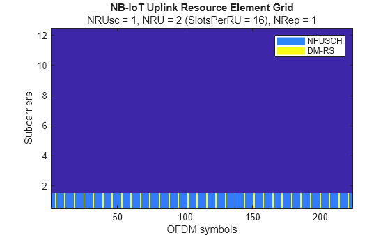
Plot Transmitted Grid
Plot the populated grid and observe the NPUSCH and corresponding DM-RS. The positions of the NPUSCH and DM-RS depends on the number of subcarriers chs.NRUsc and the subcarriers used as specified by chs.NBULSubcarrierSet. Note that the resource grid plot uses the power levels of the PUSCH and the DM-RS to assign colors to the resource elements.
% Create an image of overall resource grid
figure
im = image(abs(txgrid));
cmap = parula(64);
colormap(im.Parent,cmap);
axis xy;
title('NB-IoT Uplink Resource Element Grid');
subtitle(sprintf('NRUsc = %d, NRU = %d (SlotsPerRU = %d), NRep = %d',chs.NRUsc,chs.NRU,chs.NULSlots,chs.NRep));
xlabel('OFDM symbols')
ylabel('Subcarriers')
% Create the legend box to indicate the channel/signal types associated with the REs
reNames = {'NPUSCH';'DM-RS'};
clevels = round(db2mag([chs.NPUSCHPower chs.NPUSCHDMRSPower]));
N = numel(reNames);
L = line(ones(N),ones(N), 'LineWidth',8); % Generate lines
% Set the colors according to cmap
set(L,{'color'},mat2cell(cmap( min(1+clevels,length(cmap) ),:),ones(1,N),3));
legend(reNames{:});
Local Functions
function [ue,chs,tbs] = nbiotRMCConfiguration(rcname,nrep,subcarrieroffset,nncellid,rnti,dmrscyclicshift,duplexmode,tddconfig)
% Get the parameter configuration for the specified NPUSCH reference test channel
%
% TS 36.101, User Equipment (UE) radio transmission and reception
% Annex A.2.4 - Reference Measurement Channels for UE Category NB1
%
% TS 36.104, Base Station (BS) radio transmission and reception
% Annex A.14 - Fixed Reference Channels for NB-IoT reference sensitivity (pi/2 BPSK, R=1/3)
% Annex A.15 - Fixed Reference Channels for NB-IoT dynamic range (pi/4 QPSK, R=2/3)
% Annex A.16 - Fixed Reference Channels for NB-IoT PUSCH format 1

    % Prepare for reduced inputs
    if nargin < 2
        nrep = 1;
        subcarrieroffset = 0;
        nncellid = 0;
        rnti = 0;
        dmrscyclicshift = 0;
        duplexmode = 'FDD';
        tddconfig = 1;
        if nargin < 1
            rcname = 'A14-1';
        end
    end

    % Get primary independent parameters for the reference NPUSCH
    [ue,chs,tbs] = getBasicRMCDefinition(rcname);

    % Get number of time slots in a resource unit (NULSlots) according to TS 36.211 Table 10.1.2.3-1
    % The combination of the SCS and number of subcarriers uniquely defines the number of slots in the associated RU
    if strcmpi(chs.NPUSCHFormat,'Data')       % NPUSCH format 1
        if chs.NRUsc == 1
            NULSlots = 16;
        elseif any(chs.NRUsc == [3 6 12])
            NULSlots = 24/chs.NRUsc;  % Giving 8,4,2 slots per RU at the associated number of subcarriers
        else
            error('Invalid number of subcarriers. NRUsc must be one of 1,3,6,12.');
        end
    elseif strcmpi(chs.NPUSCHFormat,'Control') % NPUSCH format 2
        NULSlots = 4;
    else
        error('Invalid NPUSCH Format (%s). NPUSCHFormat must be ''Data'' or ''Control''',chs.NPUSCHFormat);
    end
    chs.NULSlots = NULSlots;  % Mandatory. Number of slots in single RU (deduced from NRUsc and format, and the TS 36.211 table)

    % NPUSCH channel-specific parameters - Required parameters
    numSubcarriers = 12*15/str2double(ue.NBULSubcarrierSpacing(1:end-3));
    subcarrieroffset = min(subcarrieroffset,numSubcarriers-chs.NRUsc);
    chs.NBULSubcarrierSet = subcarrieroffset+(0:chs.NRUsc-1); % Mandatory
    chs.NRep = nrep;         % Mandatory
    chs.RNTI = rnti;         % Mandatory

    chs.NPUSCHPower = 0;     % Simulation mandatory
    chs.NPUSCHDMRSPower = 0; % Simulation mandatory

    % NPUSCH channel-specific parameters - Defaulting optional parameters
    chs.CyclicShift = dmrscyclicshift; % Optional. DM-RS multi-tone (3 or 6) cyclic shift
    chs.SeqGroupHopping = 'off';       % Optional. Enable/Disable Sequence-Group Hopping for UE
    % Set the DM-RS base sequence ID according to TS 36.211 Section 10.1.4.1.2.
    % DM-RS base sequence ID is used for the multi-tone cases (3, 6, 12
    % tones), while has no effect for single-tone or disabled sequence-group hopping cases.
    if chs.NRUsc == 3
        maxBaseSeqIdx = 12;
    elseif chs.NRUsc == 6
        maxBaseSeqIdx = 14;
    else % chs.NRUsc == 12 or single tone
        maxBaseSeqIdx = 30;
    end
    chs.BaseSeqIdx = mod(nncellid,maxBaseSeqIdx); % Optional. DM-RS base sequence ID
    chs.SeqGroup = 0;                  % Optional. Delta_SS. Higher-layer parameter groupAssignmentNPUSCH
    chs.SlotIdx = 0;                   % Optional (for lteSCFDMAModulate). Initial slot index of the waveform

    % UE-wide parameters - Required parameters
    ue.NNCellID = nncellid;     % Mandatory
    ue.DuplexMode = duplexmode; % Mandatory

    % UE-wide parameters - Defaulting optional parameters
    if strcmpi(duplexmode,'TDD')
        ue.TDDConfig = tddconfig; % Optional. TDD configuration (1, 2, 3, 4, or 5 for 15kHz, and 1 or 4 for 3.75kHz)
    end

end

function [ue,chs,tbs] = getBasicRMCDefinition(rcname)
% Get the primary independent parameters for the RMC from the RAN4 RMC/FRC specification tables

    persistent rclist nl;

    if isempty(rclist)

        % TS 36.104 A.14 Fixed Reference Channels for NB-IoT reference sensitivity (pi/2 BPSK, R=1/3)
        rclistA14 = struct(...
            'RCName',compose('A14-%d',1:2),...
            'TBS',32,...
            'NBULSubcarrierSpacing',{'15kHz','3.75kHz'},...
            'NRUsc',1,...
            'Modulation','BPSK',...  % (pi/2) BPSK for single tone
            'NRU',2, ...  % Each NPUSCH instance is 2 RUs of 1x16 'subcarriers x slots x pi/2-BPSK'
            'NPUSCHFormat','Data'...
            );

        % TS 36.104 A.15 Fixed Reference Channels for NB-IoT dynamic range (pi/4 QPSK, R=2/3)
        rclistA15 = struct(...
            'RCName',compose('A15-%d',1:2),...
            'TBS',104,...
            'NBULSubcarrierSpacing',{'15kHz','3.75kHz'},...
            'NRUsc',1,...
            'Modulation','QPSK',...  % (pi/4) QPSK for a single tone
            'NRU',1, ...  % Each NPUSCH instance to 1 RU of 1x16 'subcarriers x slots x pi/4-QPSK'
            'NPUSCHFormat','Data'...
            );

        % TS 36.104 A.16 Fixed Reference Channels for NB-IoT NPUSCH format 1
        % A.16.1 One PRB
        rclistA16_1 = struct(...
            'RCName',compose('A16-%d',1:6),...
            'TBS',{32,32,40,104,136,424},...
            'NBULSubcarrierSpacing',{'3.75kHz','15kHz','15kHz','15kHz','15kHz','15kHz'},...
            'NRUsc',{1,1,3,6,12,12},...
            'Modulation',{'BPSK','BPSK','QPSK','QPSK','QPSK','QPSK'},...
            'NRU',{2,2,1,1,1,5}, ...
            'NPUSCHFormat','Data'...
            );
        % A16-7 uses 16QAM
        rclistA16_2 = struct(...
            'RCName','A16-7',...
            'TBS',280,...
            'NBULSubcarrierSpacing','15kHz',...
            'NRUsc',12,...
            'Modulation','16QAM',...
            'NRU',1, ...
            'NPUSCHFormat','Data'...
            );

        % TS 36.101, Annex A.2.4 Reference Measurement Channels for UE Category NB1
        rclistA24 = struct(...
            'RCName',compose('R-%d',1:7),...
            'TBS',{32,40,32,40,72,72,72},...
            'NBULSubcarrierSpacing',{'3.75kHz','3.75kHz','15kHz','15kHz','15kHz','15kHz','15kHz'},...
            'NRUsc',{1,1,1,1,3,6,12},...
            'Modulation',{'BPSK','QPSK','BPSK','QPSK','QPSK','QPSK','QPSK'},...
            'NRU',{2,1,2,1,1,1,1}, ...
            'NPUSCHFormat','Data'...
            );

        % Control (NPUSCH format 2) 'reference' channels (provided here for utility, not 3GPP defined)
        rclistControl = struct(...
            'RCName',compose('Control-%d',1:2),...
            'TBS',0,...
            'NBULSubcarrierSpacing',{'3.75kHz','15kHz'},...
            'NRUsc',1,...
            'Modulation','BPSK',...
            'NRU',1, ...
            'NPUSCHFormat','Control'...
            );

        % Combine all the sets of channel definitions into a single structure vector
        rclist = [rclistA14,rclistA15,rclistA16_1,rclistA16_2,rclistA24,rclistControl];
        nl = {rclist.RCName}; % Store all the RMC names contained in the above definitions
    end

    % Look-up the definition entry for the required FRC
    selection = rclist(strcmpi(rcname,nl));
    if isempty(selection)
        error('RC name must be one of %s.', join(string(nl),', '));
    end

    % Parameter field mapping function
    fv = @(y,v)setfield(y,v,selection.(v));

    % Create the UE-specific parameter structure
    ue = struct();
    ue = fv(ue,'NBULSubcarrierSpacing');

    % Create the NPUSCH channel-specific structure
    chs = struct();
    chs = fv(chs,'NPUSCHFormat');
    chs = fv(chs,'Modulation');
    chs = fv(chs,'NRUsc');
    chs = fv(chs,'NRU');

    % Return the associated TBS
    tbs = selection.TBS;

end

function cwOut = getCodewordBlock(cwIn,blockIdx)
    % Get the slice of the codeword related to the input block index
    cwOut = cwIn(:,mod(blockIdx,size(cwIn,2))+1);
end
Selected Bibliography
3GPP TS 36.211 "Physical channels and modulation"
3GPP TS 36.212 "Multiplexing and channel coding"
3GPP TS 36.213 "Physical layer procedures"
3GPP TS 36.321 "Medium Access Control (MAC); Protocol specification"
3GPP TS 36.331 "Radio Resource Control (RRC); Protocol specification"
3GPP TS 36.300 "Overall description; Stage 2"
O. Liberg, M. Sundberg, Y.-P. Wang, J. Bergman and J. Sachs, Cellular Internet of Things: Technologies, Standards and Performance, Elsevier, 2018.
3GPP TS 36.101 "User Equipment (UE) radio transmission and reception"
3GPP TS 36.104 "Base Station (BS) radio transmission and reception"