Sensorless Field-Oriented Control of PMSM Using I-F Control-Based Startup
This example implements field-oriented control (FOC) using sensorless position estimation and I-F control-based startup to control the speed of a three-phase permanent magnet synchronous motor (PMSM).
The PMSM starts using the I-F control algorithm (using the I-F Controller block) followed by transition from I-F to closed-loop control and from closed-loop to I-F control.
I-F control provides good control over torque during motor startup. Unlike open-loop control, I-F control starts the motor without any current overshoot as well as provides smooth I-F control to closed-loop control transition. For more details about the I-F control technique, see I-F Controller.
For details about FOC, see Field-Oriented Control.
This example uses the sensorless position estimation technique. You can select either the flux observer or extended EMF observer to estimate the position feedback for the FOC algorithm used in the example.
The Flux Observer block uses identical inputs  to estimate the stator flux, generated torque, and the rotor position.
The Extended EMF Observer block computes the electrical position,  (or
(or  and
and  ) in addition to the mechanical speed of the PMSM from the measured voltage and current in the stationary alpha-beta reference frame.
To ensure that the detected rotor position is accurate, add the inverter board resistance value to the stator phase resistance parameter of the motor block and the stator resistance parameter of the Flux Observer and Extended EMF Observer blocks.
The sensorless observers and algorithms have known limitations regarding motor operations beyond the base speed. It is recommended that you use the sensorless examples for operations up to base speed only.
Note: It is recommended that you run the example using floating-point data type.
Models
The example includes the target model mcb_pmsm_foc_sensorless_IFStartUp_f28379d.
You can use this model for both simulation and code generation.

For details about the supported hardware configuration, see the Required Hardware topic in the Generate Code and Deploy Model to Target Hardware section.
Required MathWorks Products
To simulate model:
Motor Control Blockset™
To generate code and deploy model:
Motor Control Blockset
Embedded Coder®
C2000™ Microcontroller Blockset
Fixed-Point Designer™ (only needed when you use fixed-point data type for optimized code generation)
Prerequisites
1. Obtain the motor parameters. The Simulink® model uses default motor parameters that you can replace with the values from either the motor datasheet or other sources.
However, if you have the motor control hardware, you can estimate the parameters for the motor that you want to use, by using the Motor Control Blockset parameter estimation tool. For instructions, see Estimate Motor Parameters Using Motor Control Blockset Parameter Estimation Tool.
The parameter estimation tool updates the motorParam variable (in the MATLAB® workspace) with the estimated motor parameters.
2. If you obtain the motor parameters from the datasheet or other sources, update the motor parameters and inverter parameters in the model initialization script associated with the Simulink models. For instructions, see Estimate Control Gains and Tune Control Parameters.
If you use the parameter estimation tool, you can update the inverter parameters, but do not update the motor parameters in the model initialization script. The script automatically extracts motor parameters from the updated motorParam workspace variable.
Simulate Model
This example supports simulation. Follow these steps to simulate the model.
1. Open a target model included with this example.
2. Use the Position Estimator button to select one of the following sensorless position estimation techniques:
3. Use the Startup current limit objective button to select the type of load at startup:
Handle dynamic load: The I-F control-based startup assumes the load to be dynamic, utilizing the maximum starting torque. Use this option if you are unsure of the exact load on the motor.
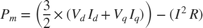
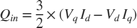
Reduced power consumption: The I-F control-based startup assumes that the load remains steady or changes slowly. Use this option to improves the efficiency of motor at startup. In this case, the I-F Controller block in the model uses the mechanical power
 and reactive power input
  as additional inputs. These two equations represent those values:
4. After selecting the appropriate Startup current limit objective, simulate the model. To do this, click Run on the Simulation tab.
5. To view and analyze the simulation results, click Data Inspector on the Simulation tab.
Generate Code and Deploy Model to Target Hardware
This section instructs you on how to generate code and run the FOC algorithm on the target hardware.
This example uses a host and a target model. The host model is a user interface to the controller hardware board. You can run the host model on the host computer. The prerequisite to use the host model is to deploy the target model to the controller hardware board. The host model uses serial communication to command the target Simulink model and run the motor in closed-loop control.
Required Hardware
This example supports these hardware configurations. You can also use the target model name to open the model for the corresponding hardware configuration, from the MATLAB command prompt.
LAUNCHXL-F28379D controller + (BOOSTXL-DRV8305 or BOOSTXL-3PHGANINV) inverter:
mcb_pmsm_foc_sensorless_IFStartUp_f28379d
For connections related to the preceding hardware configurations, see LAUNCHXL-F28069M and LAUNCHXL-F28379D Configurations.
Generate Code and Run Model on Target Hardware
1. Simulate the target model and observe the simulation results.
2. Complete the hardware connections.
3. The model automatically computes the Analog-to-Digital Converter (ADC) or current offset values. To disable this functionality (enabled by default), update the value 0 to the variable inverter.ADCOffsetCalibEnable in the model initialization script.
Alternatively, you can compute the ADC offset values and update it manually in the model initialization scripts. For instructions, see Run 3-Phase AC Motors in Open-Loop Control and Calibrate ADC Offset.
4. Open the target model for the hardware configuration that you want to use. If you want to change the default hardware configuration settings for the model, see Model Configuration Parameters.
5. Load a sample program to CPU2 of LAUNCHXL-F28379D, for example, program that operates the CPU2 blue LED using GPIO31 (c28379D_cpu2_blink.slx), to ensure that CPU2 is not mistakenly configured to use the board peripherals intended for CPU1. For more information about the sample program or model, see the Task 2 - Create, Configure and Run the Model for TI Delfino F28379D LaunchPad (Dual Core) section in Getting Started with Texas Instruments C2000 Microcontroller Blockset (C2000 Microcontroller Blockset).
6. Use the Position Estimator button to select a sensorless position estimation technique.
7. Click Build, Deploy & Start on the Hardware tab to deploy the target model to the hardware.
8. In the target model, click the mcb_pmsm_foc_host_model_f28379d.slx host model hyperlink to open the associated host model.

For details about the serial communication between the host and target models, see Host-Target Communication.
9. In the model initialization script associated with the target model, specify the communication port using the variable target.comport. The example uses this variable to update the Port parameter of the Host Serial Setup, Host Serial Receive, and Host Serial Transmit blocks available in the host model.
10. Update the Reference Speed value in the host model.
Note:
By default, the example uses the I-F to FOC transition speed (the Speed to exit I-F controller (RPM) parameter in the I-F Controller block) that is 15% of the base speed. It uses the FOC to I-F control transition speed (the Speed to re-enter I-F controller (RPM) parameter in the I-F Controller block) that is 7.5% of base speed. For more information, see I-F Controller.
High acceleration and deceleration may affect the sensorless position computation.
11. Click Run on the Simulation tab to run the host model.
12. Change the position of the Start / Stop Motor switch to On, to start running the motor in the I-F condition.
Note:
By default, the motor draws motor rated current defined by the Maximum current (A), Imax parameter of the I-F controller block. Due to the high currents drawn by the motor, it is recommended not to run the motor using I-F control for a prolonged duration.
The example considers Reference Speed values below 0.1% of rated speed as zero speed.
13. Increase the motor Reference Speed in steps to exceed Speed to exit I-F controller (parameter of the I-F Controller block) to switch from I-F control to closed-loop control.
Note: To change motor's direction of rotation, reduce the motor Reference Speed to zero and then provide a Reference Speed in the opposite direction.
14. During closed-loop operation, decrease the motor Reference Speed such that it falls below Speed to re-enter I-F controller (parameter of the I-F Controller block) to switch from closed-loop control to I-F control.
15. Observe the debug signals in the scope and display blocks available in the host model.
Note: You can also use the Debug signals section in the host model to select the signals that you want to monitor.
See Also
Flux Observer | Extended EMF Observer | Sliding Mode Observer | Pulsating High Freq Observer