Flux Observer
Compute electrical position, magnetic flux, and electrical torque of rotor
Libraries:
Motor Control Blockset HDL Support /
Sensorless Estimators
Motor Control Blockset /
Sensorless Estimators
Description
The Flux Observer block computes the electrical position, magnetic flux, and electrical torque of a surface-mount permanent magnet synchronous motor (SPMSM) or an induction motor by using the per unit voltage and current values along the α- and β-axes in the stationary αβ reference frame.
The block also accepts 16-bit fixed-point data type inputs. To perform mathematical operations on 16-bit fixed-point data type signals, the block uses optimized implementation of equations for maintaining the best possible precision.
In addition, you can use the advanced options to enable the ParameterBus input port, which you can use with the Compute Parameter block to update the block parameters optimally at run-time. You can use this functionality when motor parameters can change over time, for example, while building applications that may require swapping of motors at run-time.
Equations
These equations describe how the block computes the electrical position, magnetic flux, and electrical torque for an SPMSM in the αβ reference frame.
If and
Then, the following Laplace transforms represent the integral terms available in Ψα and Ψβ:
The block uses low-pass filter (LPF) based integrator to compute these integral terms.
If the input electrical speed of the motor (ωe) is much greater than the speed corresponding to the cutoff frequency of LPF-based integrator (ωc), then
The LPF-based integrator does not allow any DC offset (in the block inputs) to ramp up the block output. For example, consider an input function X(s)=k/s corresponding to a step input x(t) = k*u(t). Using the preceding transfer function of the LPF-based integrator, , we obtain:
According to the preceding equation, the step response of the LPF integrator asymptotically settles to a DC value (that depends on the magnitude of the step input). Whereas the step response of a pure integrator is a ramp function. Using a highpass filter at the LPF integrator output eliminates the DC offset (present in the input) completely.
These equations describe how the block computes the rotor electrical position, rotor magnetic flux, and electrical torque for an induction motor.
where:
and are the α-axis and β-axis voltages (volts).
and are the α-axis and β-axis current (amperes).
is the stator resistance of the motor (ohms).
is the stator inductance of the motor (henry).
is the rotor inductance of the motor (henry).
is the magnetizing inductance of the motor (henry).
is the total leakage factor of the induction motor.
is the number of motor pole pairs.
is the rotor magnetic flux (weber).
and are the rotor magnetic fluxes along the α- and β-axes (weber).
is the electrical torque of the rotor (Nm).
is the electrical position of the rotor (radians).
Examples
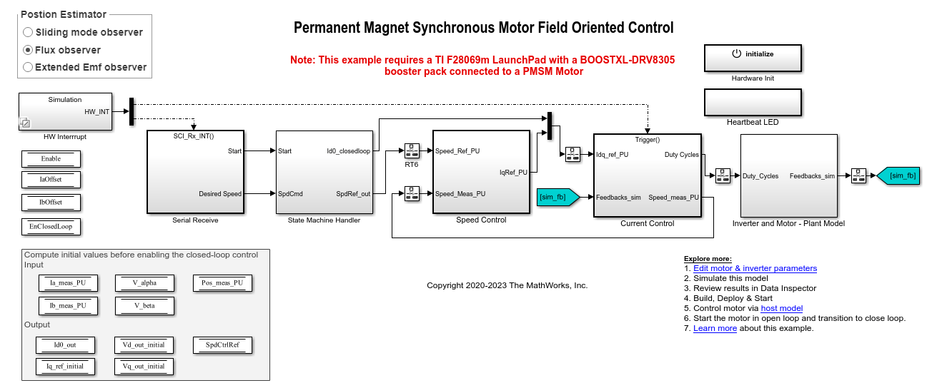
Sensorless Field-Oriented Control of PMSM
Implements the field-oriented control (FOC) technique to control the speed of a three-phase permanent magnet synchronous motor (PMSM). For details about FOC, see Field-Oriented Control.

Sensorless Field-Oriented Control of Induction Motor
Uses sensorless position estimation to implement the field-oriented control (FOC) technique to control the speed of a three-phase AC induction motor (ACIM). For details about FOC, see Field-Oriented Control.

Swap Motors with Single Deployment of Sensorless FOC Algorithm
Run a permanent magnet synchronous motor (PMSM) in an industrial drive application setup using a sensorless field-oriented control (FOC) algorithm. The example uses a sensorless Flux Observer to estimate the motor position. Industrial drives enable you to replace a motor with a new one without repeated deployment of code. An industrial drive setup needs only nameplate parameters to adapt the software to the new motor.
Ports
Input
Output
Parameters
References
[1] A. Podder and D. Pandit, "Study of Sensorless Field-Oriented Control of SPMSM Using Rotor Flux Observer & Disturbance Observer Based Discrete Sliding Mode Observer," 2021 IEEE 22nd Workshop on Control and Modelling of Power Electronics (COMPEL), 2021, pp. 1-8. (doi: 10.1109/COMPEL52922.2021.9645939)
[2] O. Sandre-Hernandez, J. J. Rangel-Magdaleno and R. Morales-Caporal, "Simulink-HDL cosimulation of direct torque control of a PM synchronous machine based FPGA," 2014 11th International Conference on Electrical Engineering, Computing Science and Automatic Control (CCE), Campeche, 2014, pp. 1-6. (doi: 10.1109/ICEEE.2014.6978298)
[3] Y. Inoue, S. Morimoto and M. Sanada, "Control method suitable for direct torque control based motor drive system satisfying voltage and current limitations," The 2010 International Power Electronics Conference - ECCE ASIA -, Sapporo, 2010, pp. 3000-3006. (doi: 10.1109/IPEC.2010.5543698)
Extended Capabilities
Version History
Introduced in R2020a