Analyze T-Coil Circuit
This example shows how to use the a linear behavioral model to analyze a T-coil impedance matching circuit and generate S-parameter data from the result.
The T-coil circuit is used in many applications to impedance match a capacitive load, such as an electrostatic discharge (ESD) protection device, over as broad a frequency band as possible [1], [2]. You need to include the effects of a T-coil circuit in the model of any broadband or microwave channel that uses it. Depending on the application, you may insert the transfer function of the circuit into a model of the channel or insert the S-parameters of the circuit into the RF analysis of the channel.
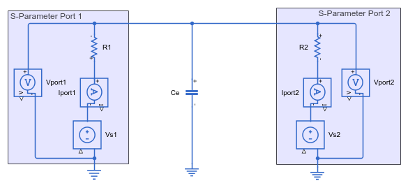
This example analyzes the T-coil circuit shown in this schematic diagram. Capacitor Ce is the capacitor to be impedance matched [3]. The schematic includes the equivalent circuits for two S-parameter ports. For more about S-parameter ports, see the S-Parameters section of the example.

This schematic has been implemented using Simscape™ blocks in the model TCoil. Open that model.
open_system("TCoil");

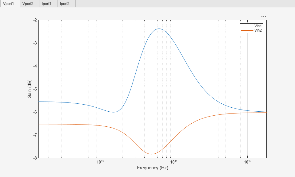
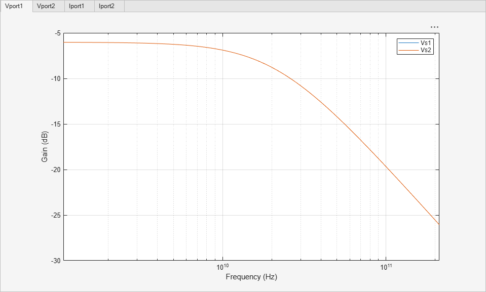
Display the frequency response of the T-coil circuit using the cktzpk function.
cktzpk("TCoil",DisplayPlot=true);
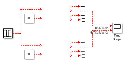
Open the model TCoilTestbench. This model contains input and output connections for you to compare two circuits.
open_system("TCoilTestbench");
Build a Linear Circuit block for the T-coil circuit using cktblock. This block implements a behavioral model of the T-coil circuit. Use TCoilTestbench as the parent model for the new block.
TCoilBlock = cktblock("TCoil","TCoilTestbench", ...
    BlockName="TCoilCircuit", ...
    CircuitDesignName="TCoil");
Connect the inputs and outputs of the new behavioral T-coil model block to the upper set of connections in TCoilTestbench.
set_param(TCoilBlock,"Position",[275 184 375 241]);
This example compares the T-coil circuit against a baseline circuit without impedance matching. The baseline circuit is a shunt capacitor connected to two S-parameter ports. The model NoTCoil contains the schematic for this circuit, implemented with Simscape™ blocks.
open_system("NoTCoil");
Display the frequency response of the baseline circuit using the cktzpk function. The response of the shunt capacitor falls off much faster at high frequencies than the response of the T-coil circuit.
cktzpk("NoTCoil",DisplayPlot=true);

Build a Linear Circuit block for the baseline circuit using cktblock. This block implements a behavioral model of the T-coil circuit. Use TCoilTestbench as the parent model for the new block.
NoTCoilBlock = cktblock("NoTCoil","TCoilTestbench", ...
    BlockName="ShuntCapacitorCircuit", ...
    CircuitDesignName="NoTCoil");
Connect the inputs and outputs of the new behavioral baseline model block to the lower set of connections in TCoilTestbench.
set_param(NoTCoilBlock,"Position",[275 303 375 362]);
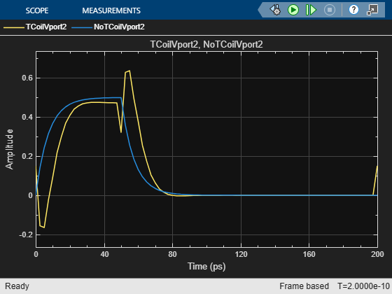
Run the simulation. In the scope display, view the pulse response of both the T-coil circuit and the unmatched shunt capacitor baseline circuit. Although the T-coil circuit introduces a little delay, the resulting pulse response is more desirable for data transmission with a flat top and more compact rising and falling edges.
sim("TCoilTestbench");
S-Parameters
The behavioral model defines ports as being either input or output and as being either voltage or current. In contrast, S-parameters are expressed in terms on incoming waves and outgoing waves at each port, based on an assumed transmission line impedance at each port. You therefore need some specific assumptions and some conversion to obtain S-parameters for a linear circuit.
The example makes these assumptions:
Each port is connected to a source/load impedance of Z0 (typically
50Ω).Each port is driven by an independent voltage source driving a resistor whose value is equal to the source/load impedance. This voltage source is an input voltage port.
The voltage at each port is available as an output. This is a voltage output port.
The current flowing through each source/load resistor is available as an output. This is a current output port.
Given these assumptions, you can transform the port node voltages and currents into incoming and outgoing waves to produce S-parameters. Given incoming wave voltage  and outgoing wave voltage
  at a port with characteristic impedance
  , and remembering that the port current is defined as an output current of the circuit, the port voltage and port current are:


Solving these equations yields the resulting waves:


The S parameter matrix is then a matrix of outgoing wave amplitudes divided by incoming wave amplitudes.
Both circuits from this example satisfy this set of assumptions for S-parameter Port 1.
V1 defines the voltage input port and R1 is the source/load resistor. Vport1 defines a voltage output port and Iport1 defines current output port whose output is the current flowing through the resistor R1.
A similar set of statements defines S-parameter Port 2.
You can calculate the S-parameter data by first defining a desired frequency scale and then using the generateSParameterData helper function provided with this example. It will parse the circuit, export poles and zeros* button, and use them to obtain the S-parameter data from DC to 100 GHz in 1 GHz steps.
frequency = (0:100)*1e9;
data = generateSParameterData("TCoil",frequency, ...
    ["Vport1","Iport1","Vin1","R1"], ... % S-Parameter port 1
    ["Vport2","Iport2","Vin2","R2"]);    % S-Parameter port 2
The resulting data structure is directly compatible with the S-parameters object and the rfwrite function in the RF Toolbox™.
tCoilSParameters = sparameters(data,frequency,50);
rfplot(tCoilSParameters);
References
Razavi, Behzad. "The Bridged T-Coil [A Circuit for All Seasons]." IEEE Solid-State Circuits Magazine 7, no. 4 (Fall 2015): 9–13. https://doi.org/10.1109/MSSC.2015.2474258.
Ross, Bob. "T-Coil Topics." DesignCon IBIS Summit, Santa Clara, Ca. February 3, 2011. https://ibis.org/summits/feb11/ross.pdf
Kossel, Marcel, Christian Menolfi, Jonas Weiss, Peter Buchmann, George von Bueren, Lucio Rodoni, Thomas Morf, Thomas Toifl, and Martin Schmatz. "A T-Coil-Enhanced 8.5Gb/s High-Swing Source-Series-Terminated Transmitter in 65nm Bulk CMOS." In 2008 IEEE International Solid-State Circuits Conference - Digest of Technical Papers, 110–599, 2008. https://doi.org/10.1109/ISSCC.2008.4523081.
See Also
Linear Circuit
Wizard | sparameters (RF Toolbox) | rfwrite (RF Toolbox)