Main Content

taylortaperc

Taylor nbar taper for arrays

Description

W = taylortaperc(pos,diam) returns the value of a Taylor n-bar taper, W, at sensor element positions specified by pos in a circular aperture having diameter diam.

example

W = taylortaperc(pos,diam,nbar) also specifies, nbar, the number of approximately constant-level sidelobes next to the mainlobe.

example

W = taylortaperc(pos,diam,nbar,sll) also specifies the maximum sidelobe level, sll, relative to the mainlobe peak.

example

W = taylortaperc(pos,diam,nbar,sll,cpos) also specifies the center of the array, cpos. Without this argument, the function sets the array center to the computed centroid of the array.

example

Examples

collapse all

Apply a Taylor nbar taper to a circular aperture array. Obtain the circular aperture by cropping a square uniform rectangular array into a circle. Let all the parameters remain at their default values: nbar is 4 and the sidelobe level is –30. Let the center of the array be the centroid of the array elements. Plot the array power pattern at 300 MHz.

Create a square URA with a side length of 10 m. Set the element spacing to 0.5 m. The spacing is equal to one-half wavelength at this frequency.

fc = 300.0e6;
diam = 10.0;
d = 0.5;
nelem = ceil(diam/d);
pos = getElementPosition(phased.URA(nelem,d));

Use the phased.ConformalArray System object™ to model a circular array. Create a circular array by removing all elements outside a radius one-half the side-length of the URA. Then apply the Taylor nbar tapering to the array.

pos(:,sum(pos.^2) > (diam/2)^2) = [];
antenna = phased.ConformalArray('ElementPosition',pos);
antenna.Taper = taylortaperc(pos,diam);

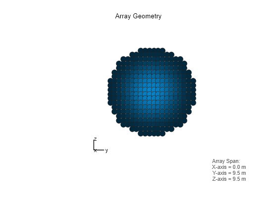
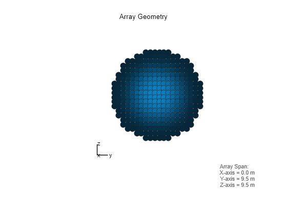
View the array.

viewArray(antenna,'ShowTaper',true)

Figure contains an axes object. The hidden axes object with xlabel x axis (Az 0 El 0) -->, ylabel y axis --> contains 7 objects of type scatter, line, text.

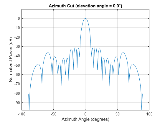
Display the array power pattern as a function of azimuth angle.

clf
pattern(antenna,fc,-90:1:90,0,'CoordinateSystem','rectangular','Type','powerdb')

Figure contains an axes object. The axes object with title Azimuth Cut (elevation angle = 0.0°), xlabel Azimuth Angle (degrees), ylabel Normalized Power (dB) contains an object of type line. This object represents 300 MHz.

Apply a Taylor nbar taper to a circular aperture array. Create the circular aperture by cropping a square uniform rectangular array into a circle. Set the value of nbar to 2. Let the sidelobe level assume a default value of –30. Let the center of the array be the centroid of the array elements. Plot the array power pattern at 300 MHz.

Create a square URA with a side length of 10 m. Set the element spacing to 0.5 m. The spacing is equal to one-half wavelength at this frequency.

fc = 300.0e6;
diam = 10.0;
d = 0.5;
nbar = 2;
nelem = ceil(diam/d);
pos = getElementPosition(phased.URA(nelem,d));

Use the phased.ConformalArray System object™ to model a circular array. Create a circular array by removing all elements outside a radius one-half the side-length of the URA. Then apply the Taylor nbar tapering to the array.

pos(:,sum(pos.^2) > (diam/2)^2) = [];
antenna = phased.ConformalArray('ElementPosition',pos);
antenna.Taper = taylortaperc(pos,diam,nbar);

View the array.

viewArray(antenna,'ShowTaper',true)

Figure contains an axes object. The hidden axes object with xlabel x axis (Az 0 El 0) -->, ylabel y axis --> contains 7 objects of type scatter, line, text.

Display the array power pattern as a function of azimuth angle.

clf
pattern(antenna,fc,-90:1:90,0,'CoordinateSystem','rectangular','Type','powerdb')

Figure contains an axes object. The axes object with title Azimuth Cut (elevation angle = 0.0°), xlabel Azimuth Angle (degrees), ylabel Normalized Power (dB) contains an object of type line. This object represents 300 MHz.

Apply a Taylor nbar taper to a circular aperture array. Create the circular aperture by cropping a square uniform rectangular array into a circle. Set the value of nbar to 4. Set the sidelobe level to –25. Let the center of the array be the centroid of the array elements. Plot the array power pattern at 300 MHz.

First, create a square URA with a side length of 10 m. Set the element spacing to 0.5 m. The spacing is equal to one-half wavelength at this frequency.

fc = 300.0e6;
diam = 10.0;
d = 0.5;
nbar = 2;
sll = -25;
nelem = ceil(diam/d);
pos = getElementPosition(phased.URA(nelem,d));

Use the phased.ConformalArray System object™ to model a circular array. Create a circular array by removing all elements outside a radius one-half the side-length of the URA. Then apply the Taylor nbar tapering to the array.

pos(:,sum(pos.^2) > (diam/2)^2) = [];
antenna = phased.ConformalArray('ElementPosition',pos);
antenna.Taper = taylortaperc(pos,diam,nbar,sll);

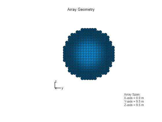
View the array.

viewArray(antenna,'ShowTaper',true)

Figure contains an axes object. The hidden axes object with xlabel x axis (Az 0 El 0) -->, ylabel y axis --> contains 7 objects of type scatter, line, text.

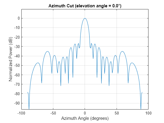
Display the array power pattern as a function of azimuth angle.

clf
pattern(antenna,fc,-90:1:90,0,'CoordinateSystem','rectangular','Type','powerdb')

Figure contains an axes object. The axes object with title Azimuth Cut (elevation angle = 0.0°), xlabel Azimuth Angle (degrees), ylabel Normalized Power (dB) contains an object of type line. This object represents 300 MHz.

Apply a Taylor nbar taper to a circular aperture array. Create the circular aperture by cropping a square uniform rectangular array into a circle. Set the sidelobe level to –25. Set the center of the array to the origin. Plot the array power pattern at 300 MHz.

Create a square URA with a side length of 10 m. Set the element spacing to 0.5 m. The spacing is equal to one-half wavelength at this frequency.

fc = 300.0e6;
diam = 10.0;
d = 0.5;
sll = -25;

Compute nbar from the sidelobe level.

A = acosh(10^(-sll/20))/pi;
nbar = ceil(2*A^2 + 0.5)
nbar = 
4

Create the URA element positions.

cpos = [0;0;0];
nelem = ceil(diam/d);
pos = getElementPosition(phased.URA(nelem,d));

Use the phased.ConformalArray System object™ to model a circular array. Create a circular array by removing all elements outside a radius one-half the side-length of the URA. Then apply the Taylor nbar tapering to the array.

pos(:,sum(pos.^2) > (diam/2)^2) = [];
antenna = phased.ConformalArray('ElementPosition',pos);
antenna.Taper = taylortaperc(pos,diam,nbar,sll,cpos);

View the array.

viewArray(antenna,'ShowTaper',true)

Figure contains an axes object. The hidden axes object with xlabel x axis (Az 0 El 0) -->, ylabel y axis --> contains 7 objects of type scatter, line, text.

Display the array power pattern as a function of azimuth angle.

clf
pattern(antenna,fc,-90:1:90,0,'CoordinateSystem','rectangular','Type','powerdb')

Figure contains an axes object. The axes object with title Azimuth Cut (elevation angle = 0.0°), xlabel Azimuth Angle (degrees), ylabel Normalized Power (dB) contains an object of type line. This object represents 300 MHz.

Input Arguments

collapse all

Position of array elements, specified as a 2-by-N or 3-by-N real-valued matrix where N is the number of elements. If pos is a 2-by-N matrix, then all elements lie in the z = 0 plane. Each column specifies the position, [x;y], of the element. If pos is a 3-by-N matrix, its columns represent the positions of array elements in [x;y;z] format. W is an N-by-1 column vector containing the Taylor tapers. The 2-by-N form is designed for planar arrays although you can use the 3-by-N form and set the third row to zero. Position units are in meters.

Example: [–5,–5,5,5;-5,5,5,-5]

Data Types: double

Array diameter, specified as a positive scalar. Diameter units are in meters.

Example: 15.5

Data Types: double

Number of nearly equal sidelobes on each side of the mainlobe, specified as a positive integer. Units are dimensionless.

Example: 3

Data Types: double

Maximum sidelobe, specified as a negative scalar. Sidelobe levels are referenced to the mainlobe. Units are in dB.

Example: -10.0

Data Types: double

Array center, specified as a real-valued 2-by-1 or 3-by-1 vector. Units are in meters. Use a 2-by-1 vector when the element positions are specified as a 2-by-N matrix. The default value is the computed centroid of all the array elements.

Example: [5;-10;3]

Data Types: double

Output Arguments

collapse all

Taylor weights, returned as a real-valued N-by-1 column vector. N is the number of array elements. Units are dimensionless.

Algorithms

collapse all

Compute Minimum Value of N-bar

A useful guideline for choosing a value of nbar that meets the required sidelobe level (sll), as specified in the sll argument, is to satisfy the inequality

n¯2π2(cosh1(10sll20))2+0.5

This is a recommendation and you may be able to use a smaller value.

References

[1] Taylor, T. “Design of Circular Aperture for Narrow Beamwidth and Low Sidelobes.” IRE Trans. on Antennas and Propagation. Vol. 5, No. 1, January 1960, pp. 17-22.

[2] Van Trees, H. L. Optimal Array Processing: Part 4 of Detection, Estimation, and Modulation Theory. New York: A. J. Wiley & Sons, Inc., 2002.

[3] Hansen, R. C. “Tables of Taylor Distributions for Circular Aperture Antennas.” IRE Trans. on Antenna and Propagation.Vol. 8, No. 1, January 1960, pp. 23-26.

[4] Hansen, R. C. “Array Pattern Control and Synthesis.” Proceedings of the IEEE. Vol. 80, No. 1, January 1992, pp. 141-151.

Extended Capabilities

Version History

Introduced in R2016b
See Also