Design Trajectory Controller for UR5e Manipulator Using Simulink and Unreal Engine Co-simulation
This example shows how to design a trajectory controller using Simulink for a UR5e Manipulator. It also shows how to simulate the controller with the UR5e Manipulator robot in Unreal Engine 3-D simulation environment.
Create a Scene in Unreal Engine
3-D simulation scene containing UR5e, sensors, and surrounding objects has been pre-configured for use in this example. You run the pre-configured scene in Unreal Engine and use it as a plant to design trajectory controller.
Download UR5e meshes from UniversalRobots Github® repository here.
Place the UR5e meshes in the "mesh" folder under "Action" directory. Unreal engine uses these meshes to create the UR5e manipulator during simulation.

To validate mesh files and load required variables into MATLAB workspace.
helperSetupSim3DScene
To learn more about modeling in Unreal Engine, see Simulation 3D Scene Configuration (Robotics System Toolbox) block documentation.
Open the Simulink model
open_system("ShapeTracingSimExample")With Simulation 3D Camera block and Simulation 3D Lidar block, you can access real time simulation sensor data such as images and point clouds from Simulink.
In this example, Simulation 3D Robot is configured to be the Universal Robot UR5e. During simulation, you can use Config input to pass joint position configuration for the manipulator.
To customize the location of sensors, double check the corresponding blocks and modify the block parameters.
Design Robot Controller in Simulink
In this example, the ShapeTracingSimExample captures the shape of a section of fuselage as point cloud data. During the first time step of simulation, the helperGenerateJointConfig function uses the point cloud data to generate a set of joint configurations for the robot to follow.
In the controller area, this set of joint configurations is passed in as input to the Minimum Jerk Polynomial Trajectory block to obtain a 6-by-1 array that represents all joint positions at each time step. The joint configuration input to the Simulation 3D robot block then moves the UR5e manipulator in the Unreal engine scene to the corresponding configuration.

Test the Controller with Unreal Engine Simulation
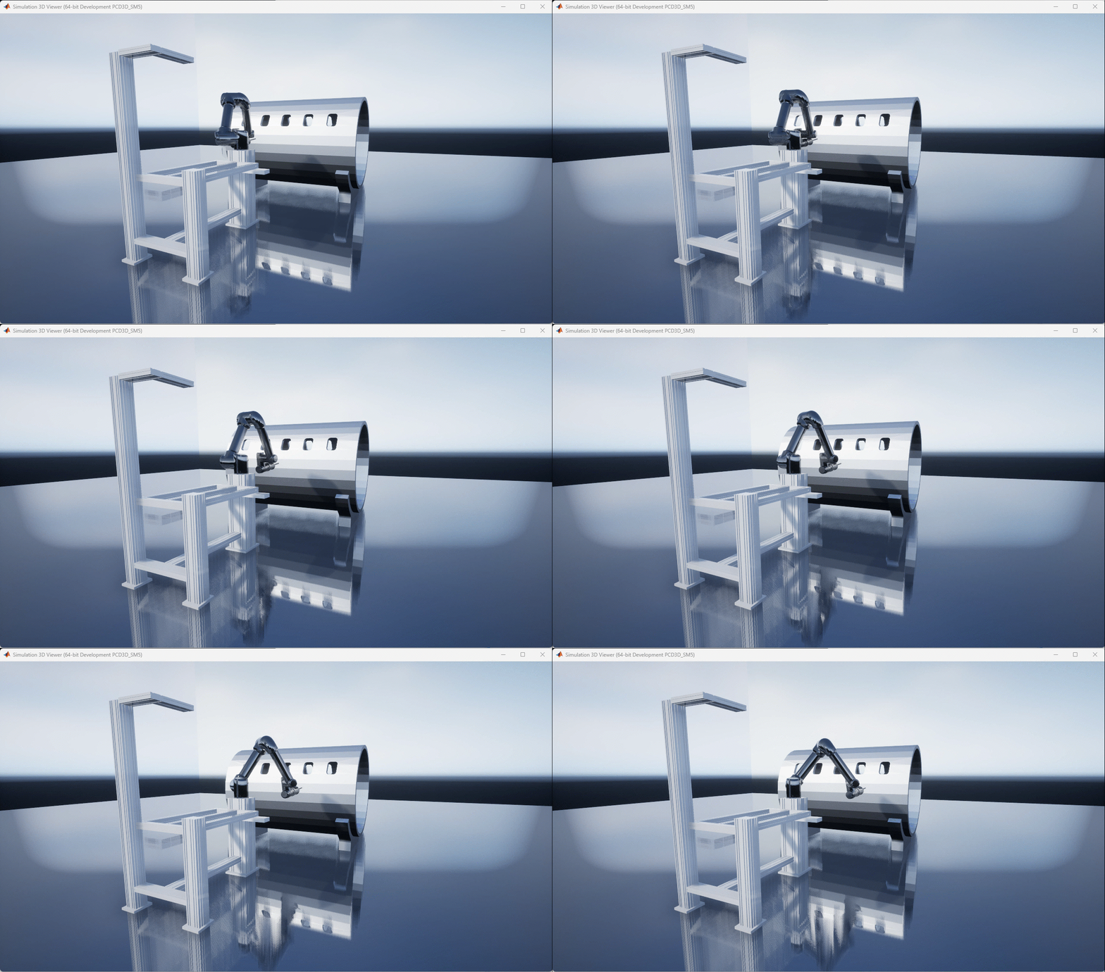
Run the simulation and observe the manipulator motion in Unreal Engine
sim("ShapeTracingSimExample")During simulation, you can
Tune the "Speed" block (Slider Gain) to control how quickly the manipulator moves
Tune the "Enable Motion" block (Constant) to decide whether to lock the joints
Observes the behavior changes in Unreal Engine scene.
