Marine Propeller

Libraries:
Simscape /
Driveline /
Engines & Motors
Description
The Marine Propeller block represents a propeller that converts a rotational mechanical motion into thrust for marine applications. You can configure the propeller with fixed or controllable blades. You can parameterize the propeller by using constants, polynomials, or tabulated data to characterize the thrust and torque coefficients. You can provide tabulated advance velocity data, or you can provide tabulated advance angle data to parameterize all four operational quadrants. Propellers that allow negative pitch or that can operate in reverse may include thrust and torque coefficient curves specific to the astern direction, which you can also specify in the block.
You can also include the wake effects of the vessel hull in the block. When you specify a constant wake fraction or enable a physical signal port, and the block calculates the wake effects automatically.
You can use a physical signal to control the blade pitch.
This terminology is helpful for understanding the block:
Wake fraction is the difference between the vessel velocity and the advance velocity expressed as a ratio of the vessel velocity.
Advance velocity is the speed of the flow through the propeller, Va.
Advance ratio is the speed of the flow through the propeller with respect to the propeller tip angular speed expressed as a ratio. The block uses this to determine kT and kQ when you set Parameterization to
Polynomial fitorTabulated data for advance ratio.Advance angle is the angular location of the propeller operational conditions on a four quadrant plot. The block uses this to determine CT and CQ when you set Parameterization to
Tabulated data for advance ratio.Quadrant is the relative two-dimensional location of the propeller operating condition where the vertical axis is Va and the horizontal axis is ω.
Pitch is the ideal translational propeller advance distance for a single revolution.
Open water is when the effects of the hull are not present.
The block equations refer to these quantities:
T is the propeller thrust.
Q is the propeller torque.
ρ is the fluid density. You can specify the fluid density using the Density parameter or the Rho port.
P is the pitch.
D is the Propeller diameter parameter, where one represents
ω is the propeller angular speed input at port R. For more information about using angular units in Simscape™, see Angular Units.
n is the propeller angular speed in revolutions per second, which consistently nondimensionalizes the torque and thrust. The block defines ω = 2πn.
nThr is the Rotational speed threshold parameter.
ε is the Propeller direction parameter.
kT is the thrust coefficient with respect to the propeller rotational speed.
kQ is the resistive torque coefficient with respect to the propeller rotational speed.
pkT is the polynomial thrust coefficient vector or 2-D matrix.
pkQ is the polynomial resistive torque coefficient vector or 2-D matrix.
CT is the thrust coefficient with respect to the relative advance velocity.
CQ is the torque coefficient with respect to the relative advance velocity.
kThr is the Saturation threshold for nondimensional coefficients parameter.
J is the advance ratio.
Va is the advance velocity. Specify the advance velocity using the Va port.
VR is the relative advance velocity at a blade section at 70% of the blade radius.
η is the efficiency.
CT* is the thrust coefficient based on the blade relative advance velocity at 70% blade radius.
CT,TLU* is the reference thrust coefficient vector or 2-D matrix.
C*Q is the torque coefficient based on the blade relative advance velocity at 70% blade radius.
C*Q,TLU is the reference torque coefficient vector or 2-D matrix.
β is the advance angle.
βTLU is the reference advance angle.
Parameterizations
The propeller performance depends on the thrust and resistive torque coefficients. The Parameterization parameter gives you different options to control these coefficients. The propeller output depends on the quadrant where the propeller operates. The block defines the four quadrants as:
First quadrant: +Va, +n
Second quadrant: +Va, -n
Third quadrant: -Va, -n
Fourth quadrant: -Va, +n
The figure shows a visual representation of the quadrants.

When you set Parameterization to
Constant coefficients, you specify the thrust and
resistive torque coefficients directly. Otherwise, the block computes these
coefficients depending on the Parameterization
setting.
When you set Parameterization to Polynomial
fit or Tabulated data for advance
ratio, the block uses the advance ratio, J.
The block uses a numerically smoothed version of the fundamental thrust and
torque equations such that
The block defines the advance ratio as
where the angular speed threshold nThr linearizes the propeller rotational speed, n, for smoothing.
When you set Parameterization to:
Polynomial fit— kT and kQ vary with time according to the values you specify for the polynomial coefficient parameters. The block saturates J to be between 0 and the first positive root of the polynomial and restricts kT and kQ to always be positive. The block calculates the thrust and torque coefficients aswhere pkT and pkQ represent the polynomial coefficients.
Tabulated data for advance ratio— You specify tabulated values for kT and kQ for given values of J or J and P/D, depending on the Blade pitch type parameter.
This basis of the propeller efficiency is the fundamental relationship
When Efficiency sensor is on, and you set
Parameterization to
Constant, the block calculates the smoothed
efficiency as
When Efficiency sensor is on, and you
set Parameterization to Polynomial
fit or Tabulated data for advance
velocity, the block calculates the smoothed efficiency as
When you set Parameterization to Tabulated
data for advance angle, the block uses thrust and torque
coefficients with respect to relative advance angle. The block defines the
advance angle as
where β is cyclic. You must ensure that the coefficient extrapolation and cycle wrapping occur as expected. The block defines the thrust and torque coefficients for relative advance velocity as
where VR is the relative advance velocity at a blade section at 70% of the blade radius, such that
Rearranging the coefficient equations yields the block equations for thrust and torque with respect to relative advance velocity:
When you set Blade pitch to:
Constant, the block calculates the thrust and torque coefficients asControlled, the block calculates the thrust and torque coefficients as
The basis of the propeller efficiency is the fundamental relationship
When Efficiency sensor is on, the block calculates the smoothed efficiency as
When you set Translational connections to
Conserving, the block uses a constant wake
fraction to relate the vessel velocity to the advance velocity. You input the
thrust and velocity of the vessel by using the R2 and
C2 ports. The block computes the advance velocity
as:
where:
V is the vessel velocity. You can specify the vessel velocity relative to the reference by using the R2 and C2 ports, where V = VR2-VC2.
w is the Wake fraction parameter.
When you set Translational connections to
Physical connections, you can use the
Va port to supply the advance velocity as a physical
signal. The block outputs the propeller thrust as a physical signal from the
Th port.
When you set Blade pitch type to
Controlled, you can parameterize the propeller
over a range of pitch-diameter ratios, P/D. You must specify
the P/D range as a vector in the Pitch-diameter
ratio vector, P/D parameter, where each element corresponds to a
row in the kT and
kQ matrices.
Inertia
You can optionally include translational and rotational propeller inertia. To
simulate inertia, set Rotational connections or
Translational connections to
Conserving, and select Model
inertia. When you select Model inertia and set
Rotational connections to
Conserving, set the initial rotational velocity or
torque on the shaft in the Initial Targets section, or set an
algebraically linked variable to high priority to initialize the rotational inertia.
When you select Model inertia and set Translational
connections to Conserving, set the initial
translational velocity or thrust in the Initial Targets
section, or set an algebraically linked variable to high priority to initialize the
translational mass.
Note
For rotational conserving connections, the block logs
Q, the aerodynamic torque, and
Inertia.t.
For translational conserving connections, the block logs
thrust, the aerodynamic thrust, and
mass.f.
You can use an Ideal Torque Sensor or Ideal Force Sensor blocks to log the sum of the inertia and the aerodynamic torque or force, respectively.
Assumptions and Limitations
The block treats the fluid velocity and propeller rotational velocity as quasi-steady in time. Fluid flows uniformly over the propeller.
When you set Parameterization to
Polynomial fit, the block assumes that the propeller torque and thrust coefficients are symmetric with the first quadrant.When you set Parameterization to
Tabulated data for advance
						ratio
, the block assumes the torque and thrust coefficients are identical in the first and third quadrants and the second and fourth quadrants.When you set Parameterization to
Tabulated
						data for advance angle
, the block removes the sign from Va. To attain negative thrusts and torques, you must include the signs in the values of CT and CQ.
Variables
To set the priority and initial target values for the block variables prior to simulation, use the Initial Targets section in the block dialog box or Property Inspector. For more information, see Set Priority and Initial Target for Block Variables.
Nominal values provide a way to specify the expected magnitude of a variable in a model. Using system scaling based on nominal values increases the simulation robustness. Nominal values can come from different sources, one of which is the Nominal Values section in the block dialog box or Property Inspector. For more information, see Modify Nominal Values for a Block Variable.
Examples
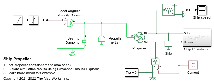
Ship Propeller
A marine propeller represented by a Propeller block from the Simscape™ Driveline™ library that propels a ship. The propeller starts from rest while the current pushes the ship forward. The ship accelerates as the Ideal Angular Velocity Source starts up the propeller. After 500 seconds, the propeller spins at a constant speed, and the ship approaches a constant speed. Ship motion is resisted by a drag force that increases quadratically with ship speed.
Ports
Inputs
Outputs
Conserving
Parameters
References
[1] Bernitsas, Michael M., D. Ray, P. Kinley. "Kt, Kq and Efficiency Curves for the Wageningen B-Series Propellers." Report 237. Department of Naval Architecture and Marine Engineering. College of Engineering. University of Michigan, 1981.
[2] Carlton, J. S. Marine Propellers and Propulsion. Second edition. Oxford: Elsevier, 2007.