Create Custom Queuing Systems Using Discrete-Event Stateflow Charts
The Discrete-Event Chart block is similar to a Stateflow® chart but is used for discrete events. You can use the block to receive, process, and send SimEvents® entities. The Discrete-Event Chart block provides graphical state transitions and MATLAB® action language to create custom SimEvents models.
The distinguishing characteristic of the Discrete-Event Chart block is that it executes in an event-based rather than time-based fashion. To model custom discrete-event systems, use these Discrete-Event Chart block behaviors:
Precise timing — The time resolution for occurrence of events can be arbitrarily precise and is not limited by the sample time of the model.
For more information, see Discrete-Event Chart Precise Timing.
Trigger on arrival — The block executes immediately on message arrival. It does not wait for the next sample time hit.
For more information, see Trigger a Discrete-Event Chart Block on Message Arrival.
Variable execution order — The block does not have a fixed sorted execution order. The order of execution depends on the run-time conditions of the model.
For more information, see Dynamic Scheduling of Discrete-Event Chart Block.
Multiple executions per time step — The block can execute zero or multiple times in a single time step.
For more information, see Dynamic Scheduling of Discrete-Event Chart Block.
Note
With SimEvents software, you can view, edit, and simulate your Discrete-Event Chart custom block within a SimEvents example model. However, to save the model you must have a Stateflow license.
For new models, without a Stateflow license, you can view and edit the model, but cannot simulate or save it.
The entities you use with discrete-event charts can be bus objects or anonymous entities.
Properties of Discrete-Event Chart
Discrete-event chart properties allow you to specify how your chart interfaces with Simulink® and SimEvents. These properties are a subset of the Stateflow chart properties.
To specify properties for a single chart:
Double-click a chart.

Right-click an open area of the chart and select Properties.
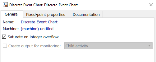
All charts provide general and documentation properties.
Observe that the chart allows the configuration of only these properties on the General tab. It also supports the Fixed-point properties and Documentation tabs.

For more information about chart properties, see Chart (Stateflow).
Note
SimEvents supports only MATLAB action language and always supports variable-size arrays.
Define Local Messages
Similar to the Stateflow chart, you can define local messages for the discrete-event chart using the Stateflow Editor or Model Explorer.
To add a local message for the discrete-event chart:
Select Symbols Pane and Create Message.
Select
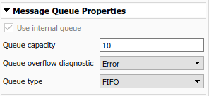
Local Messageand rename it to EntityOut.To specify local message queue properties, such as capacity, sorting policy, and overflow behavior right-click EntityLocal and select
Inspectto open Property Inspector.
Specify Message Properties
Discrete-event charts have additional properties for output messages and local messages.
| Message Input Port Properties | Description |
|---|---|
| Priority | If two message events occur at the same time, to decide which to process first, the discrete-event chart uses this priority. A smaller numeric value indicates a higher priority. |
Event Triggering
An event in Stateflow is an object that trigger actions. For more information, see Synchronize Model Components by Broadcasting Events (Stateflow).
SimEvents Discrete-Event Chart support a subset of these events:
Message
Temporal
Local
Implicit Events,
enter,exit,on,change
SimEvents Discrete-Event Chart does nor support these events:
Conditions without an event
during,tickEvent input from Simulink
Event output to Simulink
Note
The SimEvents event calendar displays and prioritizes message, and temporal events. Events of these types execute according to the event calendar schedule.
The event calendar does not display or prioritize local and implicit events. In the SimEvents environment, these events execute as dependent events of message or temporal events. For parallel states, local and implicit events execute in the state execution order.
Message Triggering
When a message or entity arrives at a message input or local queue, the discrete-event chart responds to the message as follows:
If the discrete-event chart is in a state of waiting for a message, the discrete-event chart wakes up and makes possible transitions. The chart immediately wakes up in order of message priority, processing the message with the highest priority first. For an example, see Trigger a Discrete-Event Chart Block on Message Arrival.
If the discrete-event chart does not need to respond to the arriving message, the discrete-event chart does not wake up and the message is queued.
Temporal Triggering
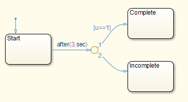
In a discrete-event chart, you can use both event-based and absolute time-based temporal logic operators. When using absolute time-based temporal logic operators, the SimEvents software uses the specified time delay value exactly. For an example, see Discrete-Event Chart Precise Timing.
For example, the activation of the temporal logic 'after(3,sec)'
causes the chart to wake up after three seconds of simulation clock time.

When using absolute-time temporal logic operators, observe these differences from the Stateflow environment.
| Operator | Description |
|---|---|
| You can use as event notation in both state actions and transitions. |
| When you use as event notation of a transition, you cannot use additional condition notations on this transition. You can apply a connective junction to check additional conditions, as long as the connective junction has one unconditional transition. |
In conditional notation, Discrete-Event Chart supports both
after and before.