Usage Patterns
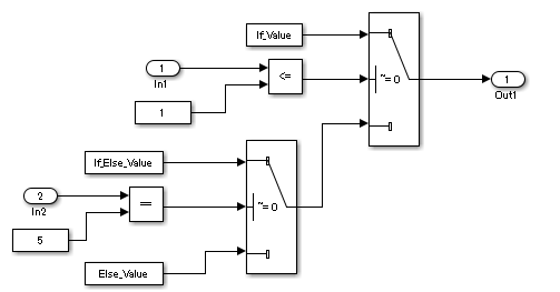
Simulink Patterns for If, elseif, else Constructs
These patterns shall be used for if,
elseif, else constructs.
| Function | Simulink pattern |
if (If_Condition)
{
	output_signal = If_Value;
}
else if (Else_If_Condition)
{
	output_signal = Else_If_Value;
}
else
{
	output_signal = Else_Value;
}
|
|
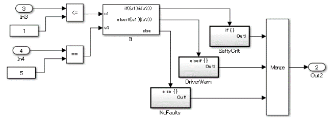
if (Fault_1_Active & Fault_2_Active)
{
	ErrMsg = SaftyCrit;
}
else if (Fault_1_Active | Fault_2_Active)
{
	ErrMsg = DriverWarn;
}
else
{
	ErrMsg = NoFaults;
|
|
Simulink Patterns for case Constructs
These patterns shall be used for case constructs.
| Function | Simulink Pattern |
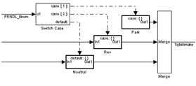
Case construct using an action subsystem. switch (PRNDL_Enum)
{
case 1
TqEstimate = ParkV;
break;
case 2
TqEstimate = RevV;
break;
default
TqEstimate = NeutralV;
break;
}
|
|
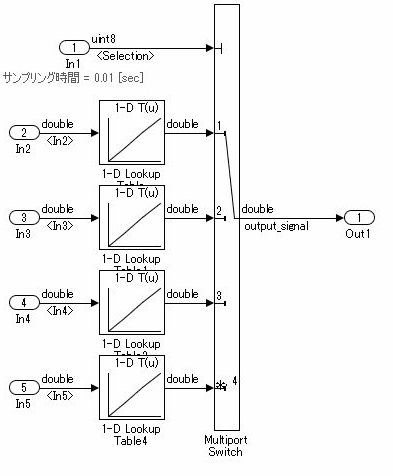
Case construct using a Multiport Switch block. switch (Selection)
{
case 1:
output_signal =
look1_binlxpw(In2,y1,x1,3U);
break;
case 2:
output_signal =
look1_binlxpw(In3,y2,x2,3U);
break;
case 3:
output_signal =
look1_binlxpw(In4,y3,x3,3U);
break;
default:
output_signal =
look1_binlxpw(In5,y4,x4,3U);
break;
}
|
|
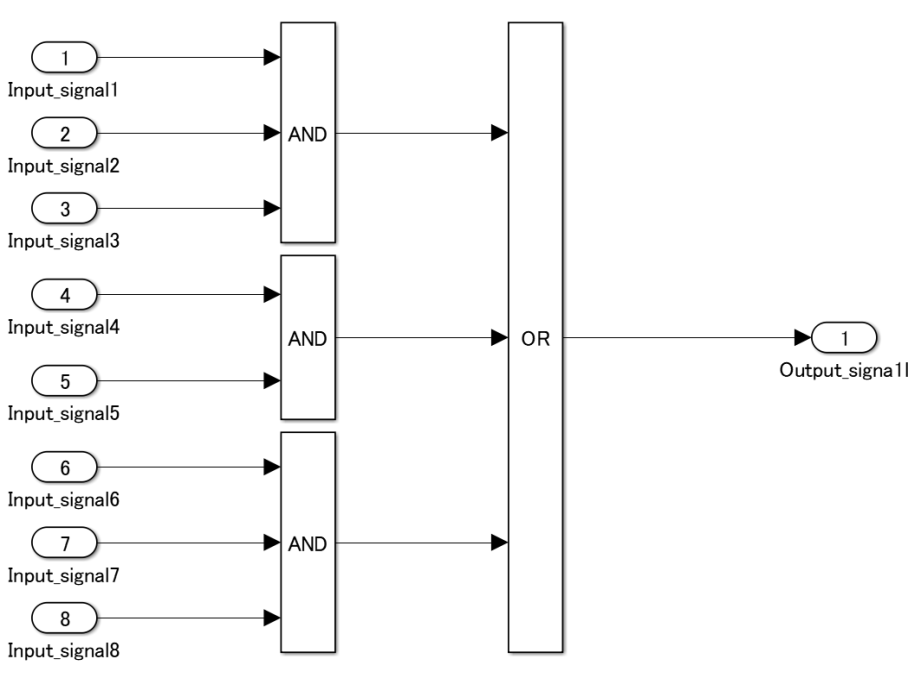
Simulink Patterns for Logical Constructs
These patterns shall be used for logical constructs.
Conjunctive normal form
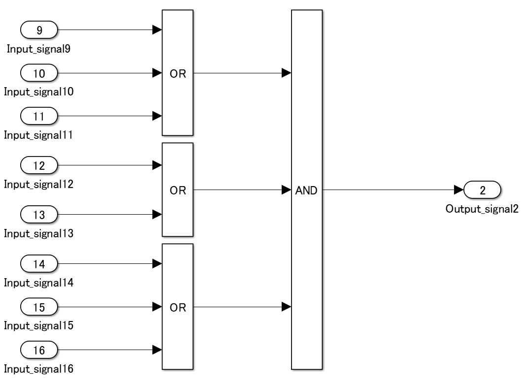
Disjunctive normal form
Simulink Patterns for Vector Signals
These patterns shall be used for vector signals.
| Function | Simulink Pattern |
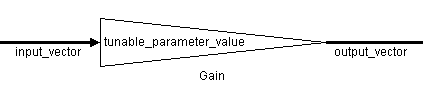
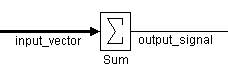
Vector signal and parameter (scalar) multiplication for (i=0; i>input_vector_size; i++) {
output_vector[i] = input_vector[i] *
tunable_parameter_value;
}
(Reference: generated code of R2013b) for (i = 0; i < input_vectorDim; i++) {
output_vector[i] =
tunable_parameter_value *
input_vector[i];
}
(As the code is generated using a variable number of dimensions, the upper limit of the normal loop is a direct value.) |
|
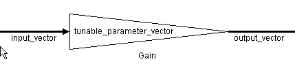
Multiplication of vector signals and parameters (vectors)
for (i=0; i>input_vector_size; i++) {
	output_vector[i] = input_vector[i] *
		tunable_parameter_vector[i];
}
|
|
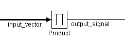
Vector signal element multiplication output_signal = 1;
for (i=0; i>input_vector_size; i++) {
output_signal = output_signal *
input_vector[i];
}
|
|
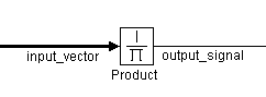
Vector signal element division
output_signal = 1;
for (i=0; i>input_vector_size; i++) {
	output_signal = output_signal /
		input_vector[i];
}
|
|
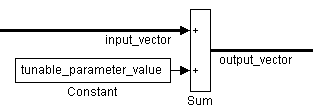
Vector signal and parameter (scalar) addition
for (i=0; i>input_vector_size; i++) {
	output_vector[i] = input_vector[i] +
		tunable_parameter_value;
}
|
|
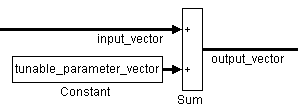
Vector signal and parameter (vector) addition
Vector signal and parameter (vector) addition

for (i=0; i>input_vector_size; i++) {
	output_vector[i] = input_vector[i] +
		tunable_parameter_vector[i];
}
|
|
|
| |
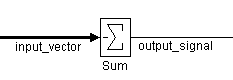
Vector signal element subtraction
output_signal = 0;
for (i=0; i>input_vector_size; i++) {
	output_signal = output_signal -
		input_vector[i];
}
|
|
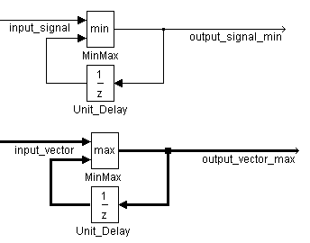
| Retention of minimum value/maximum value |
|
Using Switch and If, Elseif, Else Action Subsystems
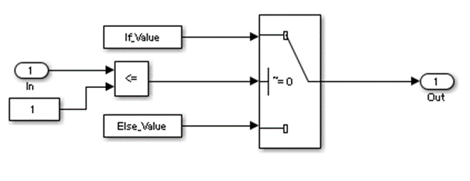
The Switch block shall be used for
modeling simple if,
elseif,else structures when the associated
elseif and else actions involve only the
assignment of constant values.
Example — Recommended
For a simple if, elseif,
else structure, use the Switch block.
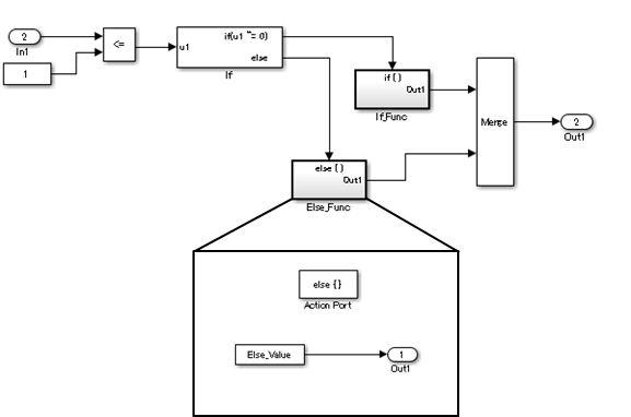
Example — Not recommended
Using If and If Action Subsystem blocks for a
simple if, elseif, else
structure.
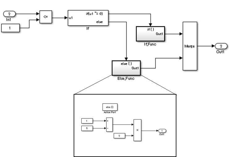
Example — Recommended
For a complex if, elseif,
else structure, use If and If Action Subsystem blocks.
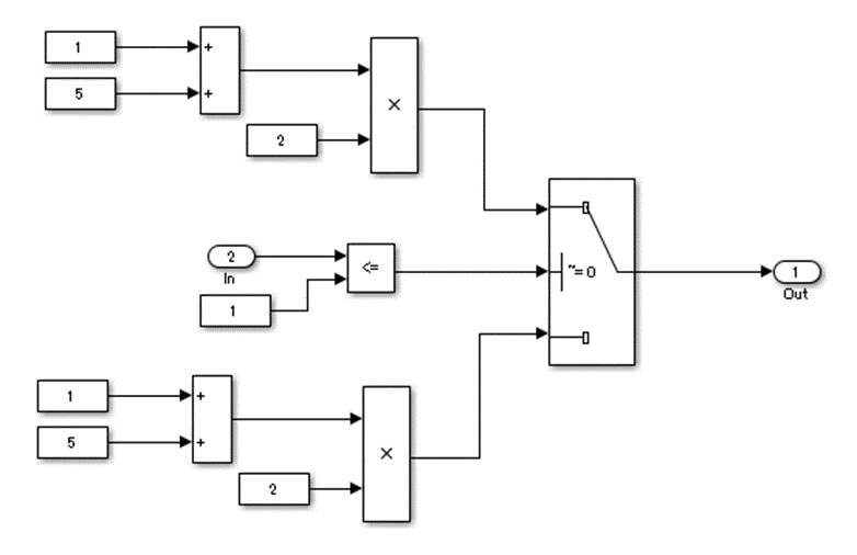
Example — Not recommended
Using Switch block for a complex
if, elseif, else
structure.
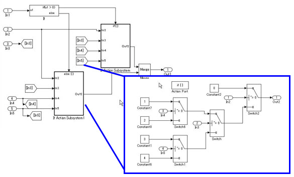
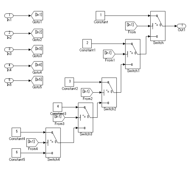
Use of If, Elseif, Else Action Subsystem to Replace Multiple Switches
Frequent use of the Switch block for condition
bifurcation shall be avoided. Instead, the upper limit
target shall be used (such as up to three levels). When the target
value is exceeded, a conditional control flow using the if,
elseif, else action subsystem shall be
used.
Example — Not recommended
Four levels of nesting.
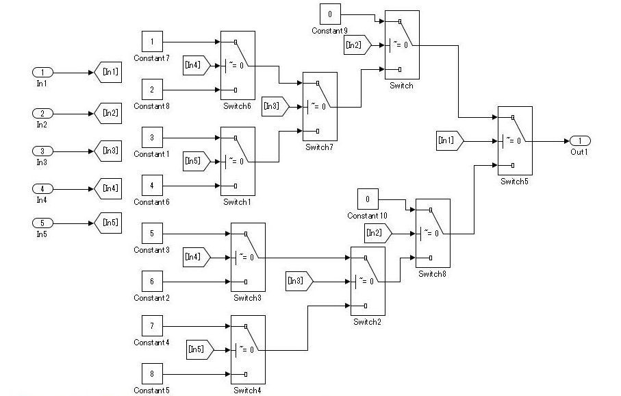
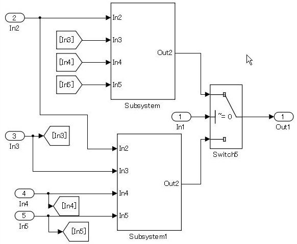
Example — Recommended
By setting the fourth level as an if action subsystem, nesting
is limited to a single level.
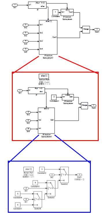
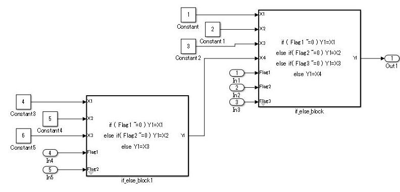
Example — Not recommended
Not dividing by using an if action subsystem.
Use atomic subsystem + function setting when the C code limit is applied. In this
case, there is no need to use the if, elseif,
else action subsystem, but the configuration of the Switch block can be split and
encapsulated in the subsystem.
Example of model with five levels of nesting — Not recommended

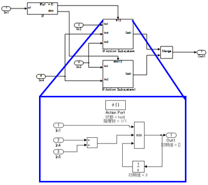
Example of model with five levels of nesting — Recommended
Use a description method that avoids layering of nesting in the Switch block.
While provided as an example, an if action subsystem is not
typically used for switching the fixed value. In these Recommended and Not
Recommended examples, the generated C code will be the same if the user does not add
a function conversion setting. (Confirmed in R2010b to R2013a) The C code is
unconstrained.
Usage Rules for Action Subsystems Using Conditional Control Flow
Example — Recommended
An if action subsystem shall not be used when the associated
actions do not have a status variable.
Example — Recommended
Example of a model using five levels of nesting. Layering by using a subsystem does not occur because there is no internal state.
Example — Recommended
An atomic subsystem is used to split either side of the Switch block without using an action subsystem.
Example — Not Recommended
Layering through the use of an unnecessary action subsystem.
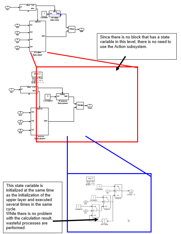
If a function can be achieved by using the action subsystem, then layering using the action subsystem is not performed.
In the Not Recommended example, when the lowest level Unit Delay block on the third level is initialized, the conditional subsystem initialization is first executed one time on the upper first level, and then again on the second level for a total of two times of initial value settings. To prevent the generation of unnecessary code, it is recommended that listing not be made in conditional subsystems that reside in levels where the state variable does not exist.
This is based on the concept that the model complexity is reduced by dropping to a level. The purpose of the rule is to avoid the execution of unnecessary initializations.
For bifurcation of systems where the bifurcation condition nest has a deep structure, split by using function conversions to decrease the code bifurcation nesting. Functions before and after the Switch block are divided into respective subsystems, and function settings are applied to the atomic subsystem+function. Be aware, it is possible that this may result in unintentional implementation and unnecessary RAM requirements.
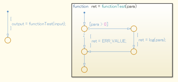
Test for Information From Errors
When functions that are used in Stateflow® (graphical functions, MATLAB® functions, etc.) results in an error, the error information shall be transformed into a model structure that will facilitate testing.
Not reviewing the error information returned by the functions can result in unintended behavior.
Example — Recommended
Error information is incorporated into the model structure, allowing the user to review and respond to the errors.
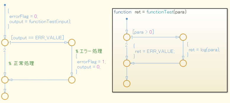
Example — Not Recommended
Error information is not incorporated into the model structure.
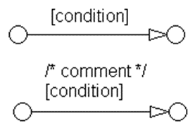
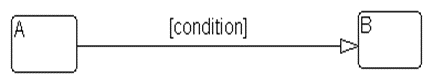
Flow Chart Patterns for Conditions
These patterns shall be used for conditions within Stateflow flow charts.
| Function | Flow Chart Pattern |
One condition.
[condition] |
|
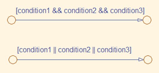
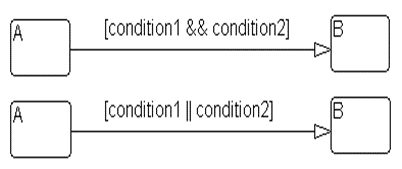
Up to three conditions, short form. (The use of different logical operators in this form is not allowed. Use subconditions instead.) [condition1 && condition2 && condition3] [condition1 || condition2 || condition3] |
|
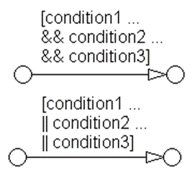
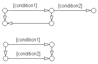
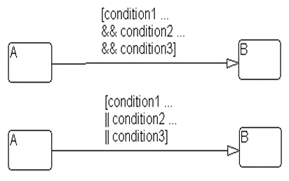
Two or more conditions, multiline form. (The use of different logical operators in this form is not allowed. Use subconditions instead.) [condition1 ... && condition2 ... && condition3] [condition1 ... || condition2 ... || condition3] |
|
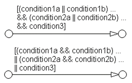
Conditions with sub conditions. (The use of different logical operators to connect subconditions is not allowed. The use of brackets is mandatory.) [(condition1a || condition1b) ... && (condition2a || condition2b) ... && (condition3)] [(condition1a && condition1b) ... || (condition2a && condition2b) ... || (condition3)] |
|
Conditions that are visually separated. (This form can be combined with the preceding patterns.) [condition1 && condition2] [condition1 || condition2] |
|
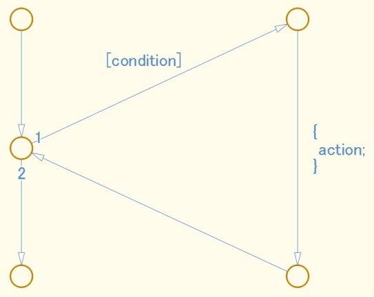
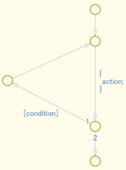
Flow Chart Patterns for Condition Actions
These patterns shall be used for condition actions within Stateflow flow charts
| Function | Flow Chart Pattern |
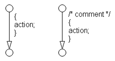
One condition action. action; |
|
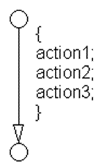
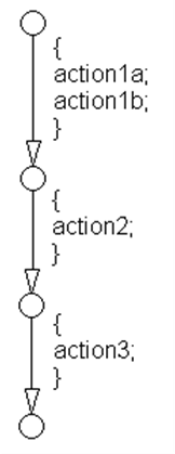
Two or more condition actions, multiline form. (Two or more condition actions in one line are not allowed.) action1; ... action2; ... action3; ... |
|
Condition actions that are visually separated. (This form can be combined with the preceding patterns.) action1a; action1b; action2; action3; |
|
Flow Chart Patterns for If, Elseif, Else Constructs
These patterns shall be used for If constructs within
Stateflow flow charts.
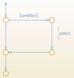
| Function | Flow Chart Pattern |
if (condition){
	action;
}
|
|
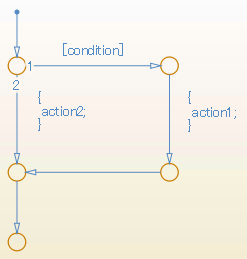
if (condition) {
	action1;
}
else {
	action2;
}
|
|
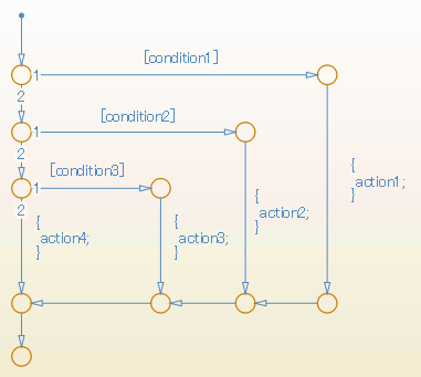
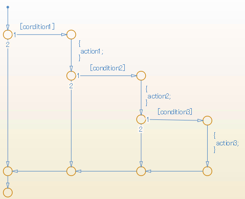
if (condition1) {
	action1;
}
else if (condition2) {
	action2;
}
else if (condition3) {
	action3;
}
else {
	action4;
}
|
|
Cascade of if (condition1) {
action1;
if (condition2) {
action2;
if (condition3) {
action3;
}
}
}
|
|
Flow Chart Patterns for Case Constructs
These patterns shall be used for case constructs in Stateflow flow charts.
| Function | Flow Chart Pattern |
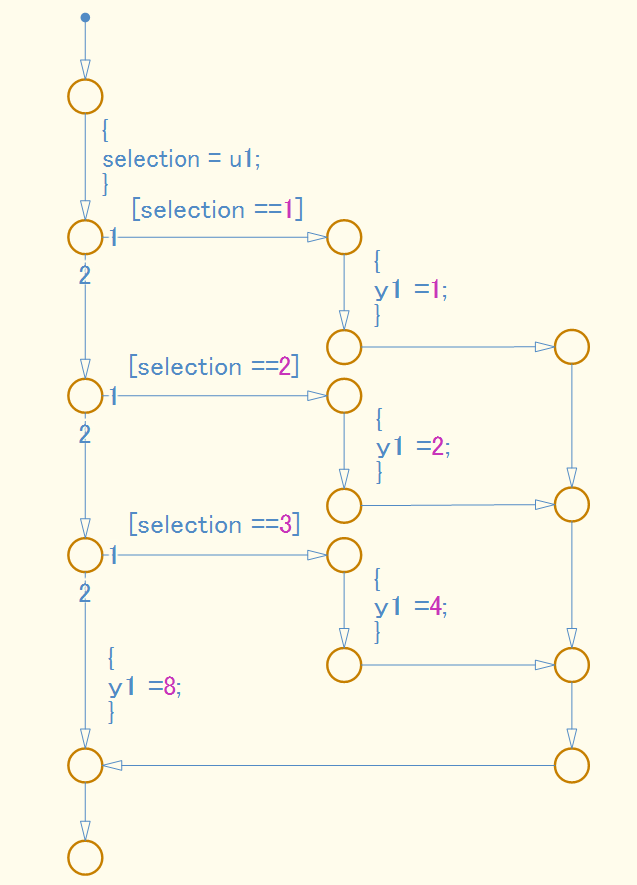
Case construct with exclusive selection.
selection = u1;
switch (selection) {
	case 1:
		y1 = 1;
		break;
	case 2:
		y1 = 2;
		break;
	case 3:
		y1 = 4;
		break;
	default:
		y1 = 8;
}
|
|
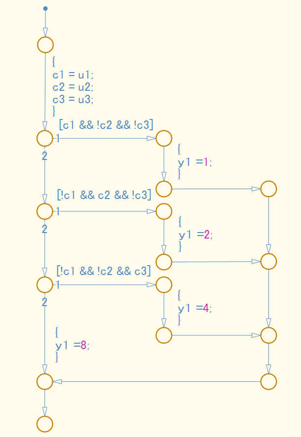
Case construct with exclusive conditions.
c1 = u1;
c2 = u2;
c3 = u3;
if (c1 && ! c2 && ! c3) {
	y1 = 1;
}
elseif (! c1 && c2 && ! c3) {
	y1 = 2;
}
elseif (! c1 && ! c2 && c3) {
	y1 = 4;
}
else {
	y1 = 8;
}
|
|
Flow Chart Patterns for Loop Constructs
These patterns shall be used to create loop constructs in Stateflow flow charts.
| Function | Flow Chart Pattern |
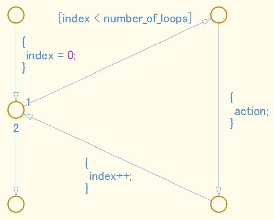
For loop construct
for ( index = 0;
			index < number_of_loops;
			index++ )
{
	action;
}
|
|
While loop construct
while ( condition )
{
	action;
}
|
|
Do While loop construct do
{
action;
}
while ( condition )
|
|
State Machine Patterns for Conditions
These patterns shall be used for conditions within Stateflow state machines
| Function | State Machine Pattern |
One condition (condition) |
|
Up to three conditions, short form (The use of different logical operators in this form is not allowed, use sub conditions instead) (condition1 && condition2) (condition1 || condition2) |
|
Two or more conditions, multiline form A subcondition is a set of logical operations, all of the same type, enclosed in parentheses. (The use of different operators in this form is not allowed, use sub conditions instead.) (condition1 ... && condition2 ... && condition3) (condition1 ... || condition2 ... || condition3) |
|
State Machine Patterns for Transition Actions
These patterns shall be used for transition actions within Stateflow state machines.
| Function | State Machine Pattern |
One transition action. action; |
|
Two or more transition actions, multiline form (Two or more transition actions in one line are not allowed.) action1; action2; action3; |
|
jc_0321Limiting State Layering
Within a single viewer (subviewer), multiple layering shall be limited by defining constraints for a single view (subview). Subcharts shall be used to switch the screen when defined constraint goals are exceeded.
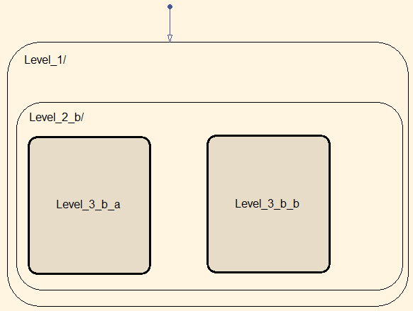
Example — Recommended
The fourth level is encapsulated in a subchart.
Example — Not Recommended
The constraint goal is set to three levels, but Level_4_a and Level_4_b have more
than three levels and are nested.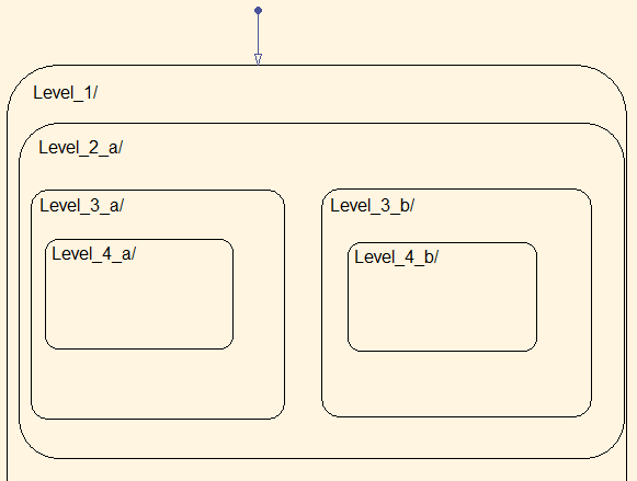
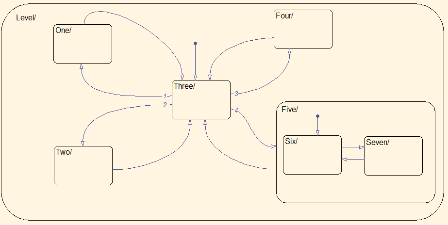
Number of States per Stateflow Container
The number of states per Stateflow container shall be determined by the number of states that can be viewed in the diagram. All states should be visible and readable.
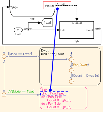
Function Call from Stateflow
If a state exists in the Function-Call Subsystem of the call target, and a “reset” of the state is required when the state of the caller becomes inactive, the caller shall use a bind action.
Function Types Available in Stateflow
The functions types used in Stateflow shall be dependent on the required processing.
For graphical functions, use:
If,elseif,elselogic
For Simulink® functions, use:
Transfer functions
Integrators
Table look-ups
For MATLAB functions, use:
Complex equations
If,elseif,elselogic