For Each Subsystem
Apply algorithm to individual elements or subarrays of input signals or mask parameters
Libraries:
Simulink /
Ports & Subsystems
HDL Coder /
Ports & Subsystems
Description
The For Each Subsystem block is a Subsystem block preconfigured as a starting point for creating a subsystem that repeats execution during a simulation time step on each element or subarray of an input signal or mask parameter array.

The set of blocks within the subsystem represents the algorithm applied to a single element or subarray of the original signal or mask parameter array. Inside the subsystem, each block that has states maintains separate sets of states for each element or subarray that it processes. Consequently, the operation of this subsystem is similar in behavior to copying the contents of the subsystem for each element in the original input signal or mask parameter array and then processing each element using its respective copy of the subsystem. As the set of blocks in the subsystem processes the elements or subarrays, the subsystem concatenates the results to form output signals.
Configure the Subsystem
The For Each Subsystem block contains a For Each block that acts as a control
block for the subsystem. Specify the parameters of the For Each block
to configure the decomposition of the subsystem inputs or mask parameters into
elements or subarrays and to configure the concatenation of the individual results
into output signals. The block parameters Partition Dimension
and Partition Width specify the dimension through which to
slice the input signal or mask parameter array and the width of each slice,
respectively. To partition a row vector, specify the Partition
Dimension as 2. To partition a column vector,
specify the Partition Dimension as 1. Use
the parameter Partition Offset to specify a gap or an overlap
between partitions. Specify a Number of iterations to limit
processing to a subset of the data. To learn more about the block parameters, see
For Each.
To specify which input signals to partition for each iteration in a for-each subsystem, use the Input Partition tab in the dialog box of the For Each block. When specifying a signal to be partitioned, specify the Partition Dimension, Partition Width, and Partition Offset parameters.
You can partition the mask parameters of a For Each Subsystem block. Partitioning is useful for systems that have identical structures in each iteration but different parameter values. In this case, changing the model to partition extra input signals for each parameter is cumbersome. Instead, add a mask parameter to a for-each subsystem. For more information, see Create a Simple Mask. To select the mask parameter for partitioning, use the Parameter Partition tab of the For Each block dialog box. For more information, see Select Partition Parameters, below.
Define the dimension along which to concatenate the results by specifying the Concatenation Dimension in the Output Concatenation tab.
The results generated by the block for each subarray are stacked along the concatenation dimension. By default, dimension 1 (y-axis) is used, meaning that the results are stacked vertically. However, if you specify a concatenation dimension of 2, the results concatenate along the horizontal direction (x-axis). Thus, if the process generates row vectors, then the concatenated result is a matrix in the first case and a row vector in the second case. For an example, see Specifying the Concatenation Dimension in the For Each Block.
When selecting an input signal or subsystem mask parameter for partitioning, you must specify how to decompose it into elements or subarrays for each iteration. Set integer values for the Partition Dimension, Partition Width, and Partition Offset parameters.
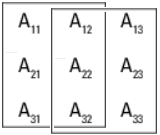
As an illustration, consider an input signal matrix A of
the form:
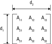
The labels d1 and
d2 define dimensions 1 and 2,
respectively. If you retain the default setting of 1 for both
the partition dimension and the partition width and 0 for the
partition offset, then Simulink® slices perpendicular to partition dimension 1 at a width equal to
the partition width, that is one element:
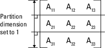
Matrix A decomposes into these three row vectors:
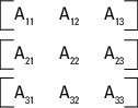
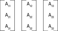
If you specify 2 as the partition dimension instead,
Simulink slices perpendicular to dimension 2 to form three column
vectors:
In addition to setting the Partition Dimension to
2, if you set the Partition Width to
2 and the Partition Offset to
-1, Simulink uses two overlapping 3-by-2 partitions for processing.
For an example, see Partitioning an Input Signal with the For Each Block.
By default, all partitions of the input signal or mask parameter are
processed. To process a subset of the partitions, enter the number of partitions
to process as the Number of iterations. In the matrix
examples above, if Partition Offset is set to
0 (the default) and Number of
iterations is set to 2, only the first 2 rows
or columns of the input matrix A are processed.
Note
Only signals are considered one-dimensional in Simulink. Mask parameters are row or column vectors, according to their orientation. To partition a row vector, specify the partition dimension as 2, along the columns. To partition a column vector, specify the partition dimension as 1, along the rows.
Code Reuse Support
For certain models, the For Each Subsystem block improves code reuse in Simulink Coder™ generated code. Consider a model containing two reusable Atomic Subsystem blocks with the same scalar algorithm applied to each element of the signal. If the input signal dimensions of these subsystems are different, Simulink Coder generated code includes two distinct functions. You can replace these two subsystems with two identical For Each Subsystem blocks that are configured to process each element of their respective inputs using the same algorithm. In this case, Simulink Coder generated code consists of a single function parameterized by the number of input signal elements. This function is invoked twice, once for each unique instance of the For Each Subsystem block in the model. For each of these cases, the input signal elements have different values.
Multicore Execution Support
When you simulate your model in rapid accelerator mode, Simulink uses multicore execution for faster simulation of for-each subsystems. Simulink automatically profiles each eligible for-each subsystem the first two time steps it runs in rapid accelerator mode to compare parallel and serial execution times. Simulink then designates the for-each subsystem for parallel, multicore execution in subsequent time steps of the simulation run if doing so would speed up execution time. For nested for-each subsystems, multicore execution applies only to the top-level subsystem. Multicore execution does not apply to for-each subsystems containing continuous states or Function Caller blocks.
To suppress multicore execution for a given for-each subsystem, set the
MultithreadedSim parameter of the For Each block within
the subsystem to
'off'.
set_param(ForEachBlockName,'MultithreadedSim','off')
Note that this is a parameter of the For Each block within the
subsystem, not the For Each Subsystem block itself. To suppress multicore
execution for all for-each subsystems in a model, set the
MultithreadedSim parameter of the model to
'off'.
set_param(ModelName,'MultithreadedSim','off')
To re-enable multicore execution, set the relevant
MultithreadedSim parameter to its default value of
'auto'.
For an example, see Multithreaded Simulation Using For Each Subsystem.
Note
If you simulate your model in rapid accelerator mode or generate code from your model, and you partition mask parameters in a for-each subsystem, then any expression inside the for-each subsystem that references a partitioned parameter must be a tunable expression. See Tunable Expression Limitations (Simulink Coder).
S-Function Support
The For Each Subsystem block supports both C-MEX S-functions and Level-2 MATLAB® S-functions, provided that the S-function supports multiple execution instances using one of these techniques:
A C-MEX S-function must declare
ssSupportsMultipleExecInstances(S, true)in themdlSetWorkWidthsmethod.A Level-2 MATLAB S-function must declare
block.SupportsMultipleExecInstances = truein the setup method.
If you use these specifications:
Do not cache run-time data such as DWork and Block I/O using global or persistent variables or within the user data of the S-function.
In a For Each Subsystem block, every S-function execution method from
mdlStartup tomdlTerminateis called once for each element processed by the S-function. Consequently, you must make sure not to free the same memory on repeated calls tomdlTerminate. For example, consider a C-MEX S-function that allocates memory for a run-time parameter withinmdlSetWorkWidths. The memory only needs to be freed once inmdlTerminate. As a solution, set the pointer to be empty after the first call tomdlTerminate.
Examples

Simulink Subsystem Semantics
This set of examples shows different types of Simulink® Subsystems and what semantics are used when simulating these subsystems. Each example provides a description of the model and the subtleties governing how the model is executed.
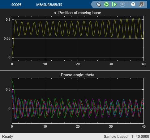
Modeling Objects with Identical Dynamics Using For Each Subsystem
Model multiple objects with identical dynamics using the For Each subsystem. The number of objects is parameterized by the length of the input signal.
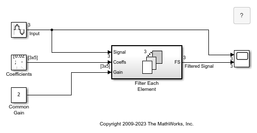
Vectorizing a Scalar Algorithm with a For-Each Subsystem
Use the for-each subsystem. In this example, the operations are performed on a vector for simplicity.
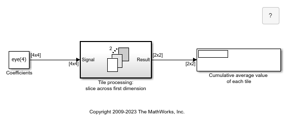
Tiled Processing of 2-D Signals with For-Each Subsystem
Use a for-each subsystem. In this example, the operations are performed on matrices.

Temperature Control System Communicating with Messages
Distributed control of room temperatures by processing messages from room thermostats and communicating control commands using messages to different receivers.

Multithreaded Simulation Using For Each Subsystem
Speed up execution of a model on multiple cores using a For Each Subsystem in Rapid Accelerator simulation.
Limitations
For information regarding limitations of the For Each Subsystem block, see Limitations of For-Each Subsystems.