Get Started with Motor Drives for Robotics Applications Using Raspberry Pi and Simulink
This example shows how to use the Simulink® Support Package for Raspberry Pi® Hardware and a Raspberry Pi hardware board to drive motors.
Introduction
Simulink Support Package for Raspberry Pi Hardware enables you to interface DC motors by configuring the GPIO pins on the Raspberry Pi Hardware board. The Raspberry Pi GPIO pins provide a current of only 16mA per pin, which is not enough to power a DC motor. To provide the required current and control directionality, you need to use a motor driver such as L298N driver. This motor driver powers the motors using an external power supply source and controls the motors based on signals from the Raspberry Pi.
This example shows you how to control the power, speed, and direction of the motor connected to the Raspberry Pi board for robotics applications. It also shows you how to control the motor using an interactive dashboard display in a Simulink model.
Prerequisites
Complete the Get Started with Simulink Support Package for Raspberry Pi Hardware example.
Required Hardware
To run this example, you will need the following hardware.
Raspberry Pi hardware board
DC Motor
Motor driver hardware such as L298 driver
Batteries
Hardware Setup
Connect the DC motor to the Raspberry Pi board through driver hardware. This example uses L298N driver for the setup and you can use any driver hardware of your choice. In this example, one DC motor is connected to the to the Raspberry Pi board through the driver hardware and the driver hardware is powered using batteries.
Connect enable pin of the driver hardware to the GPIO pin 25 of the Raspberry Pi board and configure accordingly.
The enable pins of the driver hardware control the speed of the motor. You can start or stop the motor and change its speed.
Connect the IN1 and IN2 pins of the driver hardware to the GPIO pins 23 and 24 of Raspberry Pi board and configure them accordingly.
The IN1 and IN2 pins of the driver hardware have control over the direction of the motor. You can drive the motor forward or backward using these pins.
If you use two DC motors, connect them to the L298 driver hardware, and connect the enable and input pins of the driver hardware corresponding to both the motors to the GPIO pins of the hardware board.
Simulink Model
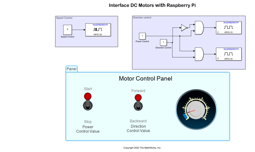
This example uses a preconfigured Simulink model from the Simulink Support Package for Raspberry Pi Hardware that consists of speed, power, and direction controls and a dashboard panel with toggle switches and knob blocks. Using this Simulink model, you can start or stop the motor and drive it in forward or backward at varying speeds.
Open the raspberrypi_robotics_motors_gettingstarted Simulink model.

The model is divided into three areas based on the functionality of the blocks in each area.
Speed Control
This subsystem is used to control the speed of the motor. Double-click on the speed control constant block to change the block parameter values. The speed control input block is connected to GPIO pin 25 on the hardware board, which is configured to provide PWM data.
Direction Control
This subsystem comprises of power and direction control blocks.
The power control block is used to start/stop the motor. This block is connected to GPIO pins configured as GPIO write pins.
The direction control block is used to drive the motor in forward/backward directions. This block is connected to GPIO pins 24 and 23 that are configured as GPIO write pins.
Motor Control Panel
This is a customizable dashboard panel that you can use to tune power, direction, and speed control parameters of the motor while the code is running on the hardware.
Run Simulink Model in Connected IO Mode
You can run the model in the connected IO mode, where the model communicates with the hardware without generating any code on the hardware.
Follow these steps to run the Simulink model in connected IO mode.
1. Open the raspberrypi_robotics_motors_gettingstarted Simulink model.
2. On the Modeling tab of the model, click Model Settings. In the Configuration Parameters dialog box, click Hardware Implementation on the left pane and set the Hardware board parameter to Raspberry Pi.
3. On the Hardware tab of the model, in the Mode section, click Run with IO.
4. You can use the dashboard panel to start or stop the motor, to move it forward or backward and to its increase the speed.
Deploy Simulink Model on Raspberry Pi Hardware
You can also deploy the Simulink model on the Raspberry Pi hardware to create a standalone system. Follow these steps to deploy the Simulink model.
1. On the Hardware tab of the Simulink model, in the Mode section, select Run on board.
2. On the Hardware settings tab of the Simulink model, in the Hardware Implementation section, select Enable deployment for Dashboard blocks.
3. In the Deploy section of the Simulink model, click Build, Deploy & Start. The generated code is built on the Raspberry Pi hardware and runs automatically.
4. Below the Simulink model, click View diagnostics to open the Diagnostic Viewer dialog box window.
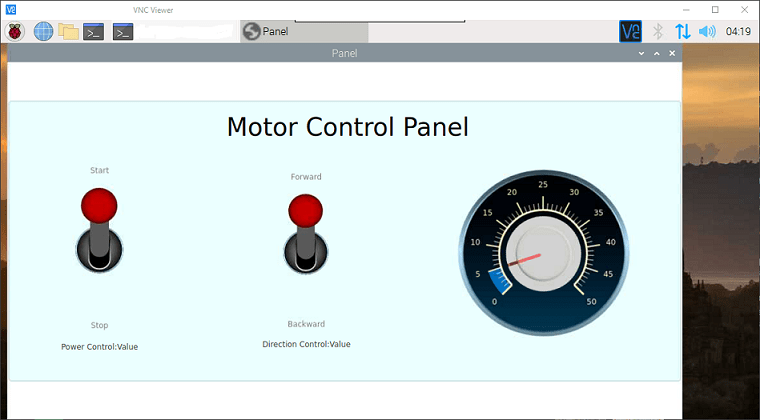
5. Click the index.html link to open the dashboard panel in a web browser after the model is successfully deployed on your Raspberry Pi hardware.
6. The dashboard panel opens in a web browser, where you can control the motor.
7. If you are using a display viewer such as VNC viewer connected to the Raspberry Pi hardware board, then the default browser opens with the dash board panel for motor control.

See Also
Get Started with Sensors for Robotics Applications Using Raspberry Pi and Simulink Online
Detect Stop Signal Traffic Sign Using Raspberry Pi and Simulink
Develop Path-Following Robot Using Raspberry Pi and Simulink
Develop Robot Navigation System Using Raspberry Pi and Simulink
Develop Obstacle Detection Robot Using ToF Sensor with Raspberry Pi