Verify a Component for Code Generation
About the Example Model
This example uses the slvnvdemo_powerwindow model to show how to verify a component in the
context of the model that contains that component. As you work through this example,
you use the Simulink®
Design Verifier™ component verification functions to create test cases and measure
coverage for a referenced model. In addition, you can execute the referenced model
in both simulation mode and Software-in-the-Loop (SIL) mode using the Code
Generation Verification (CGV) API.
Note
You must have the following product licenses to run this example:
Stateflow®
Embedded Coder®
Simulink Coder™
The component that you verify is a Model block named
control. This component resides inside the
power_window_control_system subsystem in the top level of the
slvnvdemo_powerwindow model. The
power_window_control_system subsystem is shown below.
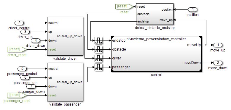
The control
Model block references the
slvnvdemo_powerwindow_controller model.
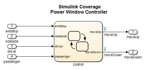
The referenced model contains a Stateflow chart control, which implements the logic for the
power window controller.

Prepare the Component for Verification
To verify the referenced model slvnvdemo_powerwindow_controller,
create a harness model that contains the input signals that simulate
the controller in the plant model:
Open the
slvnvdemo_powerwindowexample model and the referenced model:openExample('sldv/CreatingAndExecutingTestCasesExample',... 'supportingFile','slvnvdemo_powerwindow'); open_system('slvnvdemo_powerwindow_controller');
Open the
power_window_control_systemsubsystem in the example model.The Model block named
controlin thepower_window_control_systemsubsystem references the component that you verify during this example,slvnvdemo_powerwindow_controller.Simulate the Model block that references the
slvnvdemo_powerwindow_controllermodel and log the input signals to the Model block:loggedSignalsPlant = sldvlogsignals( ... 'slvnvdemo_powerwindow/power_window_control_system/control');
sldvlogsignalsstores the logged signals inloggedSignalsPlant.Generate a harness model with the logged signals:
harnessModelFilePath = sldvmakeharness( ...
	'slvnvdemo_powerwindow_controller', loggedSignalsPlant);
sldvmakeharnesscreates and opens a harness model namedslvnvdemo_powerwindow_controller_harness. The Signal Editor block contains one test case containing the logged signals.For more information about harness models, see Use Harness Model for Test Simulations.
For use later in this example, save the name of the harness model:
[~, harnessModel] = fileparts(harnessModelFilePath);
Leave all windows open for the next part of this example.
Next, you will record coverage for the slvnvdemo_powerwindow_controller model.
Record Coverage for the Component
Model coverage is a measure of how thoroughly a test case tests
a model, and the percentage of pathways that a test case exercises.
To record coverage for the slvnvdemo_powerwindow_controller model:
Create a default options object, required by the
sldvruntestfunction:runOpts = sldvruntestopts;
Specify to simulate the model, and record coverage:
runOpts.coverageEnabled = true;
Simulate the referenced model and record coverage:
[~, covDataFromLoggedSignals] = sldvruntest( ...
	'slvnvdemo_powerwindow_controller', loggedSignalsPlant, runOpts);
Display the HTML coverage report:
cvhtml('Coverage with Test Cases', covDataFromLoggedSignals);The
slvnvdemo_powerwindow_controllermodel achieved:Decision coverage: 40%
Condition coverage: 35%
MCDC coverage: 10%
For more information about decision coverage, condition coverage, and MCDC coverage, see Types of Model Coverage (Simulink Coverage).
Because you did not achieve 100% coverage for the slvnvdemo_powerwindow_controller model,
next, you will analyze the model to record additional coverage and
create additional test cases.
Use Simulink Design Verifier Software to Record Additional Coverage
You can use Simulink
Design Verifier to analyze the slvnvdemo_powerwindow_controller
model and collect coverage. You can specify that the analysis ignore any previously
satisfied objectives and record additional coverage.
To record additional coverage for the model:
Save the coverage data that you recorded for the logged signals in a file:
cvsave('existingCovFromLoggedSignal', covDataFromLoggedSignals);Create a default options object for the analysis:
opts = sldvoptions;
Specify that the analysis generate test cases to record decision, condition, and modified condition/decision coverage:
opts.ModelCoverageObjectives = 'MCDC';Specify that the analysis ignore objectives that you satisfied when you logged the signals to the Model block:
opts.IgnoreCovSatisfied = 'on';Specify the name of the file that contains the satisfied objectives data:
opts.CoverageDataFile = 'existingCovFromLoggedSignal.cvt';Specify that the analysis create long test cases that satisfy several objectives:
opts.TestSuiteOptimization = 'LongTestcases';Creating a smaller number of test cases each of which satisfies multiple test objectives saves time when you execute the generated code in the next section.
Specify to create a harness model that references the component using a Model block:
opts.saveHarnessModel = 'on';
opts.ModelReferenceHarness = 'on';
The harness model that you created from the logged signals in Prepare the Component for Verification uses a Model block that references the
slvnvdemo_powerwindow_controllermodel. The harness model that the analysis creates must also use a Model block that referencesslvnvdemo_powerwindow_controller. You can append the test case data to the first harness model, creating a single test suite.Analyze the model using Simulink Design Verifier:
[status, fileNames] = sldvrun('slvnvdemo_powerwindow_controller', ...
	opts, true);
The analysis creates and opens a harness model
slvnvdemo_powerwindow_controller_harness. The Signal Editor block contains one long test case that satisfies 74 test objectives.You can combine this test case with the test case that you created in Prepare the Component for Verification, to record additional coverage for the
slvnvdemo_powerwindow_controllermodel.Save the name of the new harness model and open it:
[~, newHarnessModel] = fileparts(fileNames.HarnessModel);
open_system(newHarnessModel);
Next, you will combine the two harness models to create a single test suite.
Combine the Harness Models
You created two harness models when you:
Logged the signals to the control Model block that references the
slvnvdemo_powerwindow_controllermodel.Analyzed the
slvnvdemo_powerwindow_controllermodel.
If you combine the test cases in both harness models, you can record coverage that gets you closer to achieving 100% coverage:
Combine the harness models by appending the most recent test cases to the test cases for the logged signals:
sldvmergeharness(harnessModel, newHarnessModel);
The Signal Editor block in the
slvnvdemo_powerwindow_controller_harnessmodel now contains both test cases.Log the signals to the harness model:
loggedSignalsMergedHarness = sldvlogsignals(harnessModel);
Use the combined test cases to record coverage for the
slvnvdemo_powerwindow_controller_harnessmodel. First, configure the options object forsldvruntest:runOpts = sldvruntestopts; runOpts.coverageEnabled = true;
Simulate the model and record and display the coverage data:
[~, covDataFromMergedSignals] = sldvruntest( ...
	'slvnvdemo_powerwindow_controller', loggedSignalsMergedHarness, ...
	runOpts);
cvhtml('Coverage with Merged Test Cases', covDataFromMergedSignals);
The
slvnvdemo_powerwindow_controllermodel now achieves:Decision coverage: 100%
Condition coverage: 80%
MCDC coverage: 60%
Execute the Component in Simulation Mode
To verify that the generated code for the model produces the same results as simulating the model, use the Code Generation Verification (CGV) API methods.
Note
To execute a model in different modes of execution, use the CGV API to verify the numerical equivalence of results. For more information about the CGV API, see Programmatic Code Generation Verification (Embedded Coder).
When you perform this procedure, the simulation compiles and executes the model code using both test cases.
Create a default options object for
sldvruncgvtest:runcgvopts = sldvruntestopts('cgv');Specify to execute the model in simulation mode:
runcgvopts.cgvConn = 'sim';Execute the
slvnv_powerwindow_controllermodel using the two test cases and theruncgvoptsobject:cgvSim = sldvruncgvtest('slvnvdemo_powerwindow_controller', ... loggedSignalsMergedHarness, runcgvopts);
These steps save the results in the workspace variable
cgvSim.
Next, you will execute the same model with the same test cases in Software-in-the-Loop (SIL) mode and compare the results from both simulations.
For more information about Normal simulation mode, see What Are SIL and PIL Simulations? (Embedded Coder).
Execute the Component in Software-in-the-Loop (SIL) Mode
When you execute a model in Software-in-the-Loop (SIL) mode, the simulation compiles and executes the generated code on your host computer.
In this section, you execute the slvnvdemo_powerwindow_controller model
in SIL mode and compare the results to the previous section, when
you executed the model in simulation mode.
Specify to execute the model in SIL mode:
runcgvopts.cgvConn = 'sil';Execute the
slvnv_powerwindow_controllermodel using the two test cases and theruncgvoptsobject:cgvSil = sldvruncgvtest('slvnvdemo_powerwindow_controller', ... loggedSignalsMergedHarness, runcgvopts);
The workspace variable
cgvSilcontains the results of the SIL mode execution.Compare the results in
cgvSilto the results incgvSim, created from the simulation mode execution. Use thecompare(Embedded Coder)for i=1:length(loggedSignalsMergedHarness.TestCases) simout = cgvSim.getOutputData(i); silout = cgvSil.getOutputData(i); [matchNames, ~, mismatchNames, ~ ] = ... cgv.CGV.compare(simout, silout); end
Display the results of the comparison in the MATLAB® Command Window:
fprintf(['\nTest Case(%d):%d Signals match, %d Signals mismatch\r'],...
	i, length(matchNames), length(mismatchNames));
As expected, the results of the two simulations match.
For more information about Software-in-the-Loop (SIL) simulations, see What Are SIL and PIL Simulations? (Embedded Coder).