Capture Simulation Data in a Test Case
Capture signal data in your test results by adding signals to the Simulation Outputs section of the test case. Each output is called a logged signal. Signals listed in Simulation Outputs appear in the test results along with signals that are already selected for logging in Simulink®. You can also log a portion of a signal by using conditional or duration triggers to start and stop logging.
You can use logged signals for data comparison in baseline criteria, equivalence criteria,
custom criteria, and for data visualization in the Simulation Data Inspector. Logged signals
enable you to further test your Simulink model without changing the model. In addition to signals from the top model,
you can also log signals from subsystems and model references. You can select signals
associated with local and global data store memory, and from data store memory that uses a
Simulink.Signal object.
Add Logged Signals When Creating a Test Harness
When you right-click a model or model component and click Test Harness > Create for <Model or Model Element>, the Create Test Harness dialog box opens. To log
all output signals of the component under test,
select Log Output Signals, which is on the Basic
Properties tab of the Create New Harness dialog for Subsystem block
diagram and library harnesses. For all other types of
harnesses, the option is on the Advanced Properties tab. Signals
that are not compatible with logging do not have a logging badge attached to them. The
compatibility is determined at compile time. After the harness is created, you can turn
off logging for a signal by opening the harness, right-clicking the signal, and
selecting Stop Logging Selected Signals. If a signal does not have
a name, it is assigned one for test execution using the format <component
under test name>:<output port number>. Unnamed propagated signals use
the name of the signal from which they propagate. To log
all test harness signals programmatically, include
'LogOutputs',true as an input to
sltest.harness.create.
Add Logged Signals in the Test Manager
To add signals:
Open the model
sltestFlutterSuppressionSystemExample.openExample('sltestFlutterSuppressionSystemExample')Use
sltest.testmanager.viewto open the Test Manager.Click Open and open the
sltestFlutterCriteriaTest.mldatxtest file.In the Test Manager, under Simulation Outputs, click Add.
In the system under test, highlight blocks or signals that you want to log. To select multiple items, click and drag a selection box over multiple items.
A dialog box appears. Select signals in the dialog box.
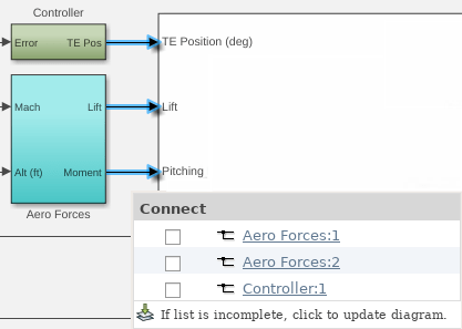
Continue adding signals to the test case. Each time you select a signal, the dialog box also shows previously logged signals. You can remove a signal from logging by clearing the selection.
When you finish adding signals, return to the Test Manager and click Done.
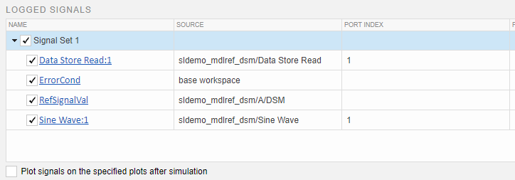
The signals appear in the Logged Signals table in the test case.

To add a signal set, click the Add arrow and select Signal Set.
To specify a specific plot for a signal, enter a number in the Plot Index column. By default, the signals appear on one plot.
You can specify to display the plot immediately after running the test by selecting the Plot signals on the specified plots after simulation check box.
After you run the test, the logged signals appear in the test case results under Sim Output. Select each signal to display on the plot. If you specify a plot index, the signal appears in the plot number you specified.
Capture Data from Local and Global Data Stores
Perform similar steps to add simulation output associated with data store memory:
Use
openExample('sldemo_mdlref_dsm')to open the model, which contains local and global data store memory.Use
sltest.testmanager.viewto open the Test Manager.Click New > Test File from Model to create a new test file.
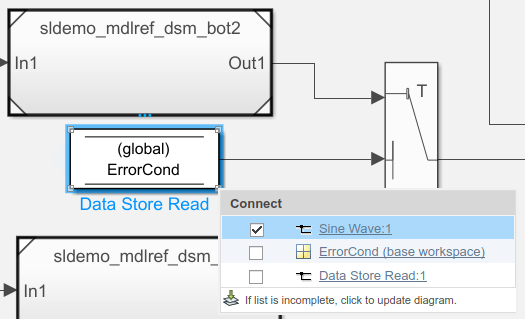
Go to the top model, select the Sine Wave block signal and click Log Selected Signal. Mark the Data Store Read (ErrorCond) block signal for logging, too.
Select the Data Store Read block in the top model. In the Modeling tab, click Update Model. The model displays the signal storage class for the block,
(global).In the Test Manager, select New Test Case 1 and expand the Simulation Outputs section. Click Add in the lower right of Logged Signals.
In the model, select the Sine Wave block and in the Connect dialog box, select Sine Wave:1. Then, select the Data Store Read block and in the dialog box, select Data Store Read: 1 and ErrorCond (base workspace).
In the model, double-click
sldemo_mdlref_dsm_botto open it. Then, open the subsystemPositiveSS. Select the Data Store Write block. The dialog box displays the input signal from the Gain block and the data store memory,RefSignalVal.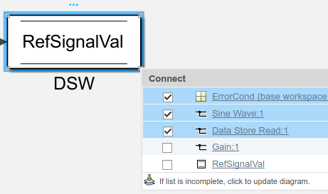
Select the
RefSignalValdata store memory for logging.Finish selecting signals by clicking Done in the Test Manager window. In the Test manager, the signals appear under Logged Signals. The Source column displays the full path information for each signal.
Log Leaf Signals of a Bus
In addition to logging an entire Bus block, you can select one or more individual signals within a bus and add them to the Logged Signals section of Test Manager. For large buses, adding only the needed signals might reduce the amount of time it takes a test case to run.
Open the model using
openExample('sldemo_absbrake').Use
sltest.testmanager.viewto open the Test Manager.Click New > Test File to create a new test file. Name and save the file.
Under System Under Test, click the Use current model icon.
Under Simulation Outputs, click Add.
In the system under test, select the signal exiting the Bus,
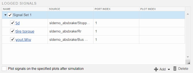
yout.A dialog box appears. Select the desired bus or bus leaf signals in the dialog box. Three horizontal lines indicate the whole bus. A single horizontal line next to a signal name indicates that it is a bus leaf signal. If the leaf signals do not appear in the dialog, click Click to update diagram.

Continue adding signals to the test case, such as the non-bus
Sdandtire torquesignalsWhen you finish adding signals, return to the Test Manager and click Done.
The signals appear in the Logged Signals table in the test case.
To add a signal set, click the Add arrow and select Signal Set.
To specify a specific plot for a signal, enter a number in the Plot Index column. By default, the signals appear on one plot.
You can specify to display the plot immediately after running the test by selecting the Plot signals on the specified plots after simulation check box.
Use Triggers to Start and Stop Signal Logging
By default, output signals are logged for the entire simulation. To specify when
signal logging starts and stops, use output triggers. An output trigger can be a
condition expression or a duration. When a condition expression evaluates to true,
logging starts or stops. The start duration is the time in seconds when logging starts
after simulation starts. The stop duration is when logging stops after signal logging
starts. To specify the triggers and the symbols to use in the conditional triggers, In
the Test Manager, use the Output Triggers subsection under
Simulation Outputs for a test case. To obtain the trigger
results programmatically, use sltest.testmanager.OutputTrigger to specify triggers, and sltest.testmanager.OutputTriggerResult to obtain the trigger results. You
must, however, use the Test Manager to define and map symbols that are used in
conditional triggers.
Add Triggers to a Test Case
This example shows how to add triggers to a test case by using the Test Manager. The triggers start logging output data when the Ww output signal is greater than 40 and stop logging output data after 4 seconds.
1. Open the model.
sldemo_absbrake
2. Open the test file in the Test Manager. This file contains a predefined test case, Trigger Test Case.
sltest.testmanager.load('AddTriggersToTest.mldatx');
sltest.testmanager.view;
3. Select Trigger Test Case and expand the Simulation Outputs section.
4. Under Output Triggers, set Start Logging to When condition is true. Then, click the edit icon next to Condition and enter Ww < 40.
5.Set Stop Logging to After Duration. Click next to Duration (sec) and enter 4. Leave Shift time to zero selected. This option shifts the logged signal so the triggered output shows as starting at time 0.

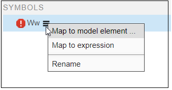
Ww appears in Symbols with a red icon, which indicates it is an unresolved symbol.
6. Point to Ww, click on the menu icon and select Map to model element.
In the model, select the Ww signal. In the Connect dialog box, select Ww.
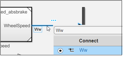
7. Return to the Test Manager and click Done. The Ww symbol updates and displays its details.

8. Run the test.
9. In the Results and Artifacts pane, display the triggered Ww output.
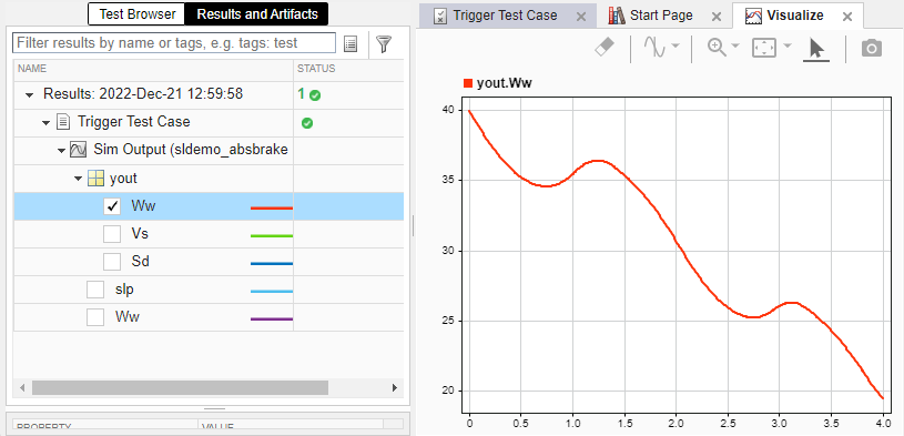
Compare the triggered output plot to the plot below, which shows the output when the entire simulation is logged. The triggered portion is highlighted. The triggered plot above is shifted to start at time 0. Logging starts when the signal equals 40 and stops 4 seconds later.
To create the plot of the entire simulation, set Start Logging to On simulation start and Stop Logging to When simulation stops.

11. To see a summary of the simulation, including the trigger information, select Trigger Test Case and expand Simulation Metadata.
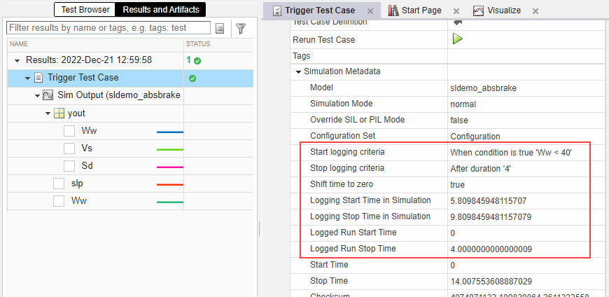
12. Clean up and close the Test Manager and close the model.
sltest.testmanager.clear
sltest.testmanager.clearResults
sltest.testmanager.close
Trigger Limitations
These limitations apply to test cases that have conditional or duration triggers enabled:
You cannot collect coverage.
If a test case has iterations, the start and stop triggers defined for the test case apply to all iterations.
See Also
sltest.testmanager.TestCase | sltest.testmanager.LoggedSignal | sltest.testmanager.LoggedSignalSet | Simulink.Signal | sltest.testmanager.OutputTrigger | sltest.testmanager.OutputTriggerResult | sltest.testmanager.TriggerMode | Simulink Test
Manager