Representing Solid Geometry
Geometry is a key attribute of solids and of the bodies they comprise. It features in the solid visualizations provided by Solid blocks as visual aides during modeling. It features also in the multibody visualizations displayed in Multibody Explorer following model assembly and during simulation. This is one purpose of solid geometry: to enable visualization for an entire modeling workflow, from the conception of a single solid to the simulation of a complete multibody model.
Geometry of a Body Element

Solid geometry serves a second, less visible, purpose: to simplify the
specification of inertia in the solid blocks. The bulk of solid inertia parameters
are readily computed if both geometry and mass, or, alternatively, mass density, are
known. The solid blocks provide an inertia parameterization, Calculate
from Geometry, that performs these calculations for you. You
specify the solid geometry and a measure of its mass; the block carries out the
required numerical integrations to obtain the remaining inertia parameters—the
moments of inertia, products of inertia, and center of mass.
Geometry in Body Elements Blocks
Solid geometry differs in a practical way from frames and inertia. The latter are attributes that you can model in isolation using blocks such as Rigid Transform and Inertia. There is no equivalent, dedicated block for solid geometry. The Graphic and Spline blocks represent geometries—and provide a visualization means for those geometries—but neither is an adequate replacement for an actual solid geometry.
The Graphic block merely adds a marker to a frame, typically as a means of highlighting that frame. The Spline block adds a plane or space curve largely intended for use with the Point on Curve Constraint block. If you want to visualize solids and bodies, or benefit from the automatic inertia calculations that solid geometry enables, you must use a solid block.
Try It: Specify a Simple Cylindrical Shape
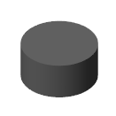
Use the Cylindrical Solid block to model a body with a simple preset shape—a cylinder with a radius of 5 cm and a length of 20 cm. Visualize the solid in the visualization pane of the Cylindrical Solid block. Ignore the relative placement of the solid in the (incomplete) model.
Add a Cylindrical Solid block to a new Simulink® model and open the block dialog box. Note the Geometry parameters section, which by default specifies a cylinder shape 1 m in side.
In the Radius parameter line, enter a value of
5and select units ofcm. You can select your units from the dropdown list or enter them manually.In the Length parameter line, enter a value of
20and again select units ofcm. Note the warning in the visualization pane urging you to update the solid visualization.In the visualization toolstrip, click the Update Visualization button. The visualization pane refreshes with the new solid geometry but, due to its small dimensions, it is barely visible. Click the Fit to View button to optimize the zoom level. Ensure that the solid geometry is as expected.
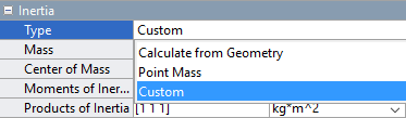
Expand the Inertia parameters section and take note of the Type parameter setting. The automatic calculation of inertia properties from geometry is by default enabled. To complete the model of your solid, you need only ensure that its mass or mass density is set to the correct value. Click OK to accept the current solid settings.
Positioning and Orienting a Solid in a Model
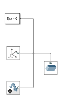
If a solid block is unconnected, the relative placement of that solid is undefined. To resolve the solid pose—its position and orientation—in a model, you must connect the reference frame port (B) or, if you prefer, a custom frame port, belonging to the solid block. For example, connecting the R port to the W port of a World Frame block would align the solid so that its reference frame is coincident with the world frame. The figure shows such a connection
Specifying spatial relationships such as this is key to modeling in the Simscape™ Multibody™ environment. You can rotate and translate two frames with respect to one another by applying operations called rigid transforms between those frames. To learn more about frames and transforms, see Working with Frames.
For ease of modeling, the solid blocks provide a frame creation interface. You can use this interface to append and align new frames to select geometry features, such as vertices, edges, faces, and volumes. To learn how to create frames using this interface, see Creating Custom Solid Frames.
Preset Solid Shapes
Solid blocks provides a sizeable array of preset shapes—those with simple parameterizations featuring readily accessible parameters, such as Radius and Length, as inputs. Preset shapes make it possible to quickly model spherical, cylindrical, and prismatic solids, among others. For greater versatility, the preset shapes include the Extruded Solid block and Revolved Solid block—shapes whose cross-sections, be they along or about an axis, you can modify. To learn more about these shapes, see Modeling Extrusions and Revolutions.
Try It: Specify a Simple Revolved Shape
Use the Revolved Solid block to model a solid of revolution—a cone with a height of 5 ft and a base radius also of 5 ft. Visualize the solid in the visualization pane of the Revolved Solid block. Ignore the relative placement of the solid in the (still incomplete) model.
Add a Revolution Solid block to a Simulink model.
In the Cross-Section parameter line, enter the coordinate matrix
[0 0; 5 0; 0 5]and select units offt. Each matrix row provides an [x z] coordinate pair, specified in that order, for a cross-section point.
Click the Update Visualization button and the Fit to View button. Ensure that the solid geometry is as expected. Click OK to accept the new solid geometry and close the block dialog box.

Specifying the Solid Cross-Sections
The Revolved Solid block generates the revolved shape by sweeping the specified xz cross-section about the z-axis. To consistently generate a valid shape without errors, the Revolved Solid block enforces a few rules. Foremost among these is the requirement that, as you proceed from one point in the coordinate matrix to the next, the solid region lie to your left and the empty (or hollow) region to your right. The same rule applies to extruded shapes, with one distinction: the cross-section coordinates are (x, y) pairs and the cross-section lies in the xy plane.
Try It: Import a STEP Geometry File
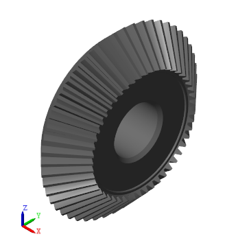
Use the File Solid block to import a detailed bevel gear geometry. The gear geometry was created in CAD software and subsequently exported in STEP format. Visualize the solid in the visualization pane of the Solid block and ignore the relative placement of the solid in the model.
Add a File Solid block to a Simulink model.
To use the STEP file, open this example and add the support folder to the search path for the current MATLAB® session:
openExample('sm/DocImportGearSTEPExample')
addpath(genpath('DocImportGearSTEPSupport'))
In the File Name parameter field, enter
BevelC.step. Specify a desired density for the part because this STEP file does not contain a density.Click the Update Visualization button and then the Fit to View button. Ensure that the solid geometry is as expected. Click OK to accept the new solid geometry and close the block dialog box.
Obtaining the Solid Geometry Files
You can obtain a STEP or STL geometry file from a CAD model. Most CAD applications enable you to export your part geometries in these (among other) formats. If you are adept at using a CAD application, or have the support of someone who is, you can create a detailed solid geometry in CAD, export it in a STEP or STL file, and import the final geometry file into a File Solid block.
If you lack a license to a professional CAD application, open-source software such as FreeCAD may provide a suitable alternative. Onshape, a professional, full-cloud CAD application, provides free subscription plans. This tool has the advantage of allowing you to import complete multibody assemblies into the Simscape™ Multibody™ environment using the smexportonshape function. For more information, see Onshape Import.
Compound Solid Shapes
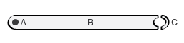
If you cannot obtain a STEP or STL file with the desired solid geometry, you can still approximate that geometry—by combining simpler preset shapes into a larger, compound, shape. You must use multiple Solid blocks—one for each preset solid shape. Often, you must also use Rigid Transform blocks, to specify the spatial relationships that exist between the solid reference frames. The figure shows a solid geometry that you can model as a compound shape—a binary link with a hole section (labeled A), a main section (B), and a peg section(C).
For an example showing how to model this compound body, see Create a Compound Geometry.