Analyze Sensorless Observers for Field-Oriented Control Using Multiple Cores of Infineon AURIX
This example shows how to use SoC Blockset™ Support Package for Infineon® AURIX™ Microcontrollers for sensorless field-oriented control using multiple cores of an Infineon AURIX microcontroller board. This example uses a top-level model and two referenced models. You use the TriCore0 referenced model to implement a sensor-based field-oriented control (FOC) technique to control the speed of a three-phase brushless DC (BLDC) motor. You use the TriCore1 referenced model to implement and analyze different sensorless algorithms such as the algorithms implemented in the Flux Observer (Motor Control Blockset), Sliding Mode Observer (Motor Control Blockset) and Extended EMF Observer (Motor Control Blockset) blocks.
The benefits of using a multicore workflow include:
Utilizing the auxiliary core to analyze different sensorless observers without affecting the sensor-based model.
Concurrently simulating more than one model with the plant.
Using the setup in this example, you can compare the observers for:
Speed response to a change in the reference step speed
Accuracy of the estimated position
Stability analysis of speed output with load impact
Noise analysis
This example also shows how to use the multiple cores of Infineon AURIX TC4x board to achieve design modularity. After simulating the models, you can deploy the code on an Infineon AURIX TC4xx TriBoard using the SoC Builder tool and monitor the signals from the hardware using the One Eye tool from Infineon.
Prerequisites
For more information on multicore modeling with SoC Blockset, see Getting Started with Multicore Modeling and Targeting for Infineon AURIX TC4x Microcontrollers.
For more information on single core motor control, see Field-Oriented Control of BLDC with Encoder Using Infineon AURIX Microcontrollers.
Required Hardware
Infineon AURIX™ TC4x-TriBoards
AURIX™ TC3xx Motor Control Power Board
Nanotec DB42S02 Electric motor
WEDL5541-B14-KIT (5 mm) Incremental Encoder
Hardware Connection
Connect the hardware as shown in this diagram.

Open Top-Level Model
The example includes the top-level model that you can use for system-level simulation of multiple cores with a plant.
Open the top-level tc4x_soc_foc_top.slx model.
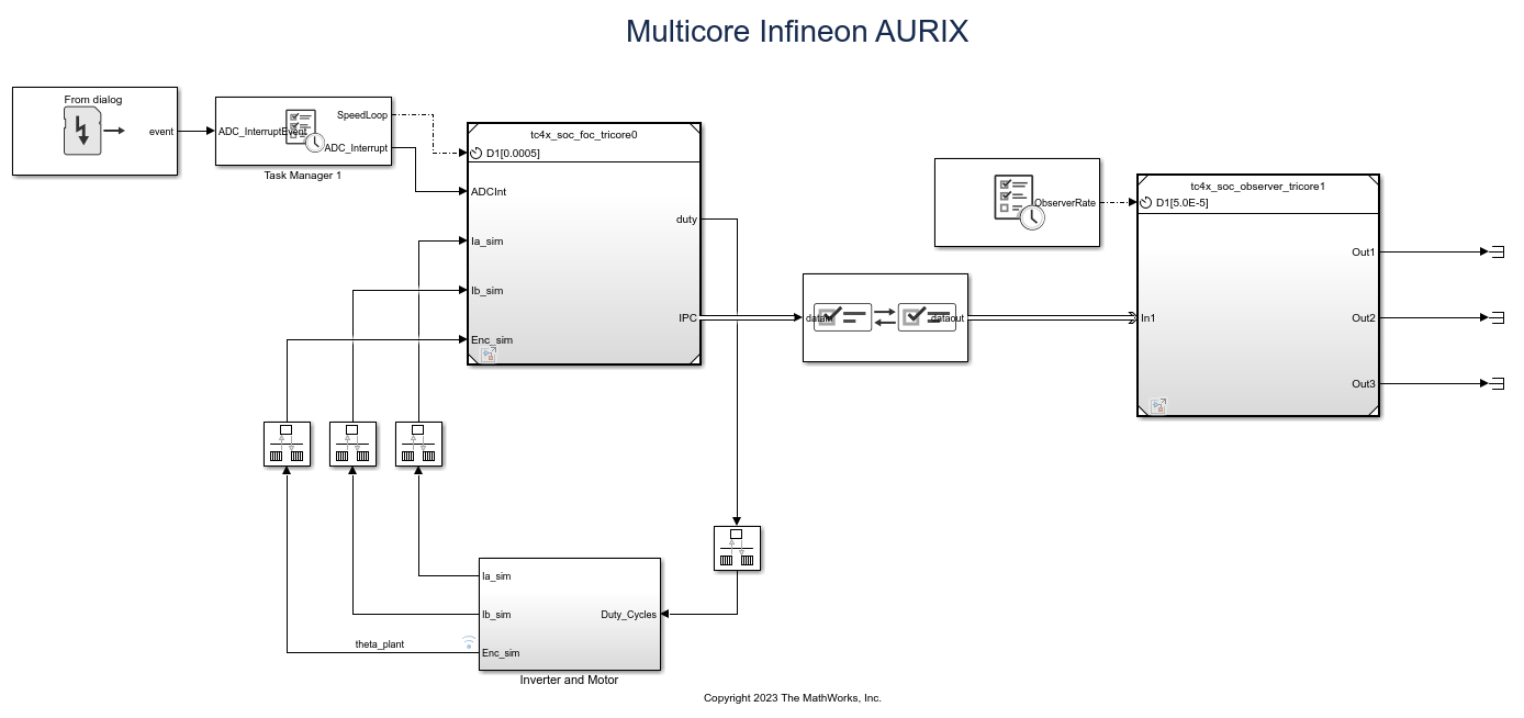
The top-level model in this example comprises of the two referenced models using TriCore0 and TriCore1 processing units. Sensor-based FOC runs on TriCore0, and different sensorless observers run on TriCore1. Data transfer between the TriCore0 and TriCore1 handled by the Interprocess Data Channel block. For more information, see Interprocess Data Communication via Dedicated Hardware Peripheral (IPC). The TriCore1 functions as an auxiliary core allowing for the analysis of different sensorless observers under various load and test conditions without affecting the sensor-based model running in TriCore0. Analyze multiple signal outputs from sensor and sensorless algorithms and select the most suitable observer for your application based on the obtained results.
Open the TriCore0 referenced model tc4x_soc_foc_tricore0.slx.

Open the TriCore1 referenced model tc4x_soc_observer_tricore1.slx.

Configure the Top-Level Model
1. Open the tc4x_soc_foc_top.slx model.
2. Press Ctrl+E or click Modeling > Model Settings to open the Configuration Parameters dialog box.
3. In the Hardware Implementation pane, set Hardware board to Infineon AURIX™ TC4x - TriBoards and Processing Unit to None.

Configure the TriCore0 and TriCore1 Referenced Models
1. Open the tc4x_soc_foc_tricore0.slx model.
2. Press Ctrl+E or click Modeling > Model Settings to open the Configuration Parameters dialog box.
3. Select Hardware Implementation pane and set Hardware board to Infineon AURIX™ TC4x - TriBoards and Processing Unit to TriCore0.

4. Open the tc4x_soc_observer_tricore1.slx model.
5. Press Ctrl+E or click Modeling > Model Settings to open the Configuration Parameters dialog box.
6. In the Hardware Implementation pane, set Hardware board to Infineon AURIX™ TC4x - TriBoards and Processing Unit to TriCore1.

7. To view scheduling port in the Model block connected to Task Manager block, right click on core specific Model block and go to Block Parameters (Model Reference) to enable Schedule rates.

Simulate Model
Complete the following steps to simulate the model.
1. Open tc4x_soc_foc_top.slx model.
2. Click Run on the Simulation tab to simulate the model.
3. Click Data Inspector on the Simulation tab to view and analyze the basic signal simulations such as speed feedback and outputs from the sensorless algorithms (flux observer, sliding mode observer, and extended EMF observer).

4. In the Task Manager block, select the Enable task simulation parameter to log and visualize the task execution and CPU utilization in Simulation Data Inspector.

Generate Code and Deploy Model to Target Hardware
Complete the following steps to generate code and run the model on the target hardware.
1. Click Configure, Build, Deploy & Start on the Hardware tab to launch the SoC Builder tool.

2. In SoC Builder, prepare the model by first specifying the folder to use for project generation. Click Next.
3. In the Review Hardware Mapping section, click View/Edit to confirm the hardware mapping. Click Next
4. In the Validate Model section, click Validate to check the model for your board (Infineon AURIX TC4x - Triboards). If the message - Model validation successfully finished - appears, click Next.
5. In the next section Build Model, click Build. This process generates the binary executable. Click Next after the build is successful.
6. Connect the hardware board to the host computer.
7. In the SoC Builder screen, click Load and Run. to load the generated binary to the connected board, program the processor, and run the application. Click Finish to close SoC Builder.
8. Download and install the One Eye tool from Infineon to monitor signals from the hardware. Before using the One Eye tool, ensure that you download and install the latest version of the DAS tool.
9. Open the One Eye tool. Load the OneEye configuration file tc4x_soc_tricore0_and_tricore1_debug.OneEye shipped with this example by clicking File > Load Configuration in the One Eye tool. You can view the tc4x_soc_foc_top_sw_TriCore0.elf configuration file in the TriCore0_Debug dialog box corresponding to the TriCore0 model. Similarly, you can view the tc4x_soc_foc_top_sw_TriCore1.elf configuration file in the TriCore1_Debug dialog box corresponding to the TriCore1 model.
Reset the hardware and check the DAS connection status to monitor the signals.

10. Observe ADC interrupt task duration from the logged variable cpuTicks_ISR_duration.

11. After successfully building the models, SoC Builder generates the core-specific models in the soc_prj folder. You can use the core-specific models to directly build and tune the core-specific models on the respective cores without going through SoC Builder. If there are task-level or interprocessor communication (IPC) changes that are impacting the system model tc4x_soc_foc_top.slx, then follow the SoC Builder workflow.

Open and Closed-Loop Control
In this example, you start with open loop for 0.5 seconds and then switch to closed-loop control.
To enable the open-loop mode, set the global variable EnableClosedLoop to 0 using the One Eye tool. To switch back to the closed-loop mode, set the variable to 1.

Calculate Encoder Offset
Your motor might stop when you switch to closed-loop control due to an incorrect encoder offset value. To calculate the encoder offset, complete the following steps.
1. Set the global variable CalculateEncoderOffset to 1 using the One Eye tool.
2. Observe the motor spinning for 1 second in open-loop mode when the rotor is locked to measure the encoder offset from the global variable theta_m.
3. Use this measured encoder offset value to set the global variable EncOffset during run-time.
4. Set the CalculateEncoderOffset variable to 0 to switch back to the closed-loop mode.
5. To use an accurate encoder offset value, update the msm.PositionOffset variable in the tc4x_soc_foc_data.m file with the value that you calculated in the previous step. You can access the data file tc4x_soc_foc_data.m from the example workspace along with the models.

Run Monitor and Tune to log signals in Simulink
1. Click Configure, Monitor & Tune on the Hardware tab of tc4x_soc_foc_top model to launch SoC Builder and follow the steps.

2. In the Select Build Action step, select Build and load for external mode to monitor the motor operation from Simulink®.
3. Open the Simulation Data Inspector and observe the speed command and motor speed response.
Known Limitations
This example model does not support simulation in Accelerator and Rapid Accelerator modes due to the lack of support for peripheral blocks in these modes.
You cannot update the run-time signal during simulation. For more information on parameter tunability, see Tunability Considerations and Limitations for Other Modeling Goals.
You cannot mux the signals from the top-level model to the reference model.
See Also
Sensorless Field-Oriented Control of PMSM (Motor Control Blockset)
You can also select a web site from the following list:
Americas
- América Latina (Español)
- Canada (English)
- United States (English)
Europe
- Belgium (English)
- Denmark (English)
- Deutschland (Deutsch)
- España (Español)
- Finland (English)
- France (Français)
- Ireland (English)
- Italia (Italiano)
- Luxembourg (English)
- Netherlands (English)
- Norway (English)
- Österreich (Deutsch)
- Portugal (English)
- Sweden (English)
- Switzerland
- United Kingdom (English)