DC Machine
(To be removed) Implement wound-field or permanent magnet DC machine
The Specialized Power Systems library will be removed in R2026a. Use the Simscape™ Electrical™ blocks and functions instead. For more information on updating your models, see Upgrade Specialized Power System Models to use Simscape Electrical Blocks.
Libraries:
Simscape /
Electrical /
Specialized Power Systems /
Electrical Machines
Description
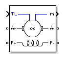
The DC Machine block implements a wound-field or permanent magnet DC machine.
For the wound-field DC machine, you can access the field terminals (F+, F−) to use the machine model as a shunt-connected or a series-connected DC machine. The Simulink® input TL provides the torque applied to the shaft.
The armature circuit (A+, A−) consists of an inductor La and resistor Ra in series with a counter-electromotive force (CEMF) E.
The CEMF is proportional to the machine speed.
| E = KEω | (1) |
KE is the voltage constant and ω is the machine speed.
In a separately excited DC machine model, the voltage constant KE is proportional to the field current If:
| KE = LafIf, | (2) |
Laf is the field-armature mutual inductance.
The electromechanical torque that the DC Machine block develops is proportional to the armature current Ia.
| Te = KTIa, | (3) |
KT is the torque constant. The sign convention for Te and TL is:
| Te ,
TL > 0: Motor
mode Te, TL < 0: Generator mode | (4) |
The torque constant is equal to the voltage constant.
| KT = KE. | (5) |
The armature circuit is connected between the A+ and A− ports of the DC Machine block. It is represented by a series Ra La branch in series with a Controlled Voltage Source and a Current Measurement block.
In the wound-field DC machine model, the field circuit is represented by an RL circuit. It is connected between the F+ and F− ports of the DC Machine block.
In the permanent magnet DC machine model, there is no field current as the magnets establish the excitation flux. KE and KT are constants.
The mechanical part computes the speed of the DC machine from the net torque applied to the rotor. The block uses the speed to implement the CEMF voltage E of the armature circuit.
The mechanical part implements this equation:
where J is the inertia, Bm is the viscous friction coefficient, and Tf is the Coulomb friction torque.
Ports
Input
Output
Conserving
Parameters
Configuration
Option to choose a set of predetermined electrical and mechanical parameters for various DC machine ratings of power (HP), DC voltage (V), rated speed (rpm), and field voltage (V).
Select one of the preset models to load the
corresponding electrical and mechanical parameters
in the entries of the dialog box. Select
No if you do not want
to use a preset model, or if you want to modify
some of the parameters of a preset model.
When you select a preset model, the electrical and mechanical parameters in the Parameters section of the dialog box become unmodifiable (unavailable). To start from a given preset model and then modify machine parameters:
Select the preset model that you want to initialize the parameters.
Change the Preset model parameter value to
No. This does not change the machine parameters. By doing so, you break the connection with the particular preset model.Modify the machine parameters as you want, then click Apply.
Dependencies
To enable this parameter, set
Field type to
Wound.
Torque applied to the shaft or the rotor speed as a Simulink input of the block, or represent the machine shaft by a Simscape rotational mechanical port:
Torque TL— Specify a torque input, in N*m. The block determines the machine speed by using the machine Inertia J and the difference between the applied mechanical load torque TL and the internal electromagnetic torque Te. The sign convention for the mechanical torque is: when the speed is positive, a positive torque signal indicates motor mode and a negative signal indicates generator mode.Speed w— Specify a speed input, in rad/s. The block imposes the machine speed and ignores the mechanical part of the model (inertia J). Use the speed as the mechanical input to model a mechanical coupling between two machines.The next figure indicates how to model a stiff shaft interconnection in a motor-generator. The speed output of machine 1 (motor) is connected to the speed input of machine 2 (generator), while machine 2 electromagnetic torque output Te is applied to the mechanical load torque input TL of machine 1. The Kw factor takes into account speed units of both machines (rad/s) and gear box ratio. The KT factor takes into account torque units of both machines (N.m) and machine ratings. Also, as the inertia J2 is ignored in machine 2, J2 referred to machine 1 speed must be added to machine 1 inertia J1.
Mechanical rotational port— Add to the block a Simscape mechanical rotational port that allows connection of the machine shaft with other Simscape blocks having mechanical rotational ports.The next figure indicates how to connect an Ideal Torque Source block from the Simscape library to the machine shaft to represent the machine in motor mode, or in generator mode, when the rotor speed is positive.
Whether to model a wound-field machine or a permanent magnet DC machine.
Measurement output
Whether to use the signal names in the measurement output to identify the bus labels. Select this parameter for applications that require bus signal label to have only alphanumeric characters.
When you clear this parameter, the measurement output uses the signal definition to identify the bus labels. The labels contain non alphanumeric characters that are incompatible with some Simulink applications.
Parameters
Armature resistance Ra, in ohms, and armature inductance La, in henries.
Field resistance Rf, in ohms, and field inductance Lf, in henries.
Dependencies
To enable this parameter, in the
Configuration section, set
Field type to
Wound.
Field-armature mutual inductance, in henries.
Dependencies
To enable this parameter, in the
Configuration section, set
Field type to
Wound.
For a permanent magnet DC machine, select the machine constant that you want to specify for block parameterization.
Dependencies
To enable this parameter, in the
Configuration section, set
Field type to
Permanent
magnet.
Voltage per speed constant of the permanent magnet DC machine, in V/rpm.
Dependencies
To enable this parameter, in the
Configuration section, set
Field type to
Permanent magnet and,
in the Parameters section,
set Specify to
Back-emf
                                                  constant
.
Torque per current constant of the permanent magnet DC machine, in N.m/A.
Dependencies
To enable this parameter, in the
Configuration section, set
Field type to
Permanent magnet and,
in the Parameters section,
set Specify to
Torque constant.
Total inertia of the DC machine, in kg.m2.
Total friction coefficient of the DC machine, in N.m.s.
Total Coulomb friction torque constant of the DC machine, in N.m.
Initial speed for the DC machine, in rad/s, in order to start the simulation with a specific initial speed. To start the simulation in steady state, the initial value of the input torque signal TL must be proportional to the initial speed.
Advanced
Sample time that the block uses. To inherit
the sample time specified in the Powergui block,
set this parameter to
−1.
References
[1] Analysis of Electric Machinery, Krause et al., pp. 89–92.
Extended Capabilities
Version History
Introduced before R2006a