On-Board Charger for Two-Wheeler Electric Vehicle
This example shows how to model an on-board charger for a two-wheeler vehicle by using an AC-DC converter and a DC-DC converter to achieve unity power factor (UPF) operation and constant current (CC) battery charging.
Efficiency plays a crucial role in the design of an on-board charger due to space constraints. This application requires specific converter topologies that allow the charger to achieve higher efficiency. The estimation of the harmonics injected into the grid helps to evaluate the grid compliance.
You can use this example to design the on-board charger and estimate its efficiency and harmonics.
Model Overview

This example comprises three main components: the grid, the on-board charger, and the EV battery. The charger is rated at 1 kW, 230 V, and 50 Hz. The EV battery is a 60V, 50Ah/3kWh Li-ion battery. The intermediate capacitor and battery charging current are maintained at 400V and 16.67A respectively.
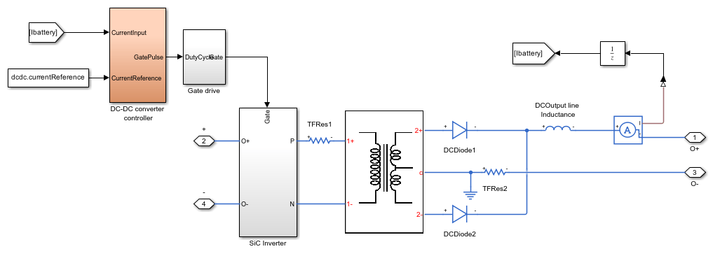
This figure shows the circuit for the on-board charger:
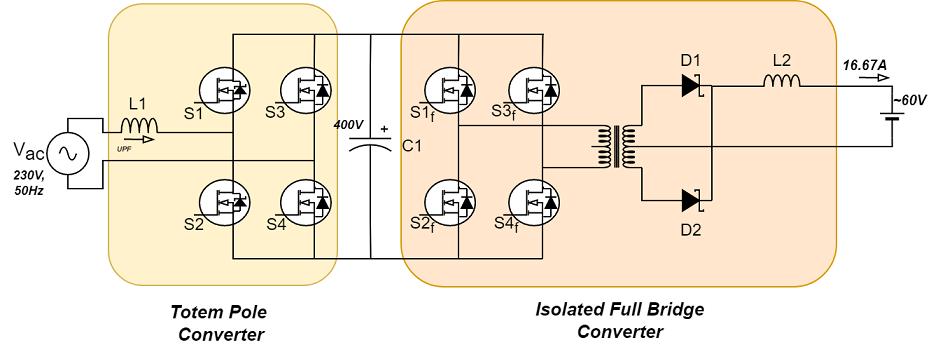
For a two wheeler vehicle, this example models the AC-DC converter by using a totem pole converter instead of a boost PFC converter due to its higher efficiency. The converter is rated at 400 V and 10 A.
To provide galvanic isolation between the battery and the grid, this example uses an isolated full bridge converter. The high-frequency inverter connected to the primary side of the transformer is rated at 400 V and 6 A. The diodes connected to the secondary side of the transformer are rated at 150 V and 20 A.
The I-V characteristics and the switching loss curves of the devices parameterize the Mosfet (Ideal, Switching) and Diode blocks. The TwoWheelerOnboardChargerSwitchData MAT file contains the device parameters and the I-V curve data of the semiconductor devices in the model. You can obtain this data from the selected device datasheet.
Totem Pole Converter
A totem pole converter is a derived topology of a boost-PFC converter and it achieves higher efficiency compared to all the other boost-PFC derived topologies.
This figure shows the circuit for the totem pole converter:
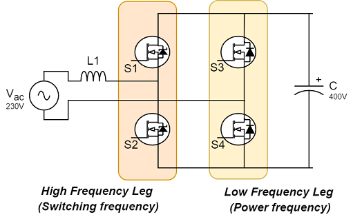
A totem pole converter comprises a high-frequency leg and a low-frequency leg. The high-frequency leg operates at the switching frequency. The high-frequency legs use wide band gap (WBG) devices due to faster switching times and low switching energy.
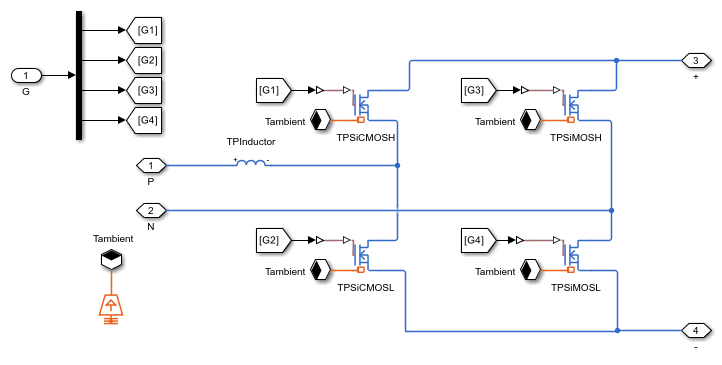
The low-frequency leg operates at power frequency. Low-frequency legs use silicon-based diodes or MOSFETs for unidirectional or bidirectional power flow. The model in this example uses silicon carbide (SiC) and silicon (Si) based MOSFETs for the high-frequency and low-frequency legs.
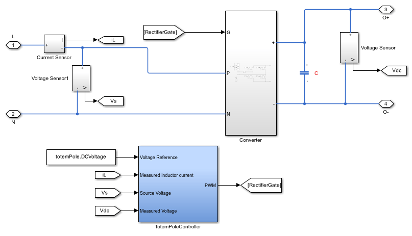
The controller achieves the unity power factor (UPF) at supply terminals and maintains the intermediate capacitor voltage at a set value.
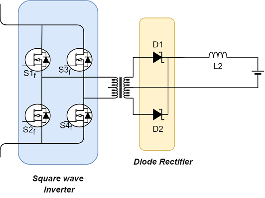
Isolated Full Bridge Converter
This example models the DC-DC converter by using an isolated full bridge converter topology. This is a double-ended topology and has higher power capability. It comprises three components: a square-wave inverter, a centre tapped transformer to improve the efficiency of the converter, and a diode rectifier. The diode rectifier uses Schottky diodes due to their lower reverse recovery losses.
The controller maintains the output current at a reference value to emulate the constant current mode of the battery charging.
This figure shows the circuit for an isolated full bridge converter:
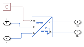
You can model the isolated DC-DC converter with three fidelity levels:
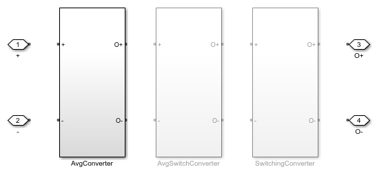
Average fidelity - This variant achieves fastest simulation times with slight reduction in accuracy in transient condition. This is the default option.
Averaged Switching - This variant uses averaged switching to achieve a faster simulation time. You can use this fidelity level to verify the operation of the converter.
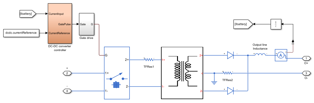
Switching - Use this variant to calculate converter losses and to estimate its efficiency.
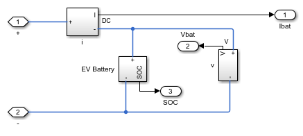
EV Battery Pack Overview
The EV battery pack models the battery cells connected in series and in parallel and the sensors that measure the battery terminal voltage and output current. A Battery (Table-based) block from the Simscape™ Electrical™ library models the individual cell of the battery back. The Battery (Table-based) block uses the Panasonic NCRBD18650 pre-parameterization, which is rated at 3.6 V, 3.03 Ah. The configuration of the batteries in the battery pack meets the required voltage and ampere-hour specifications.
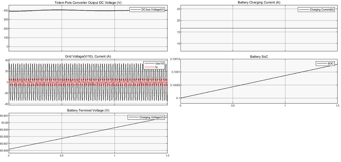
Simulation Results from Simscape Logging
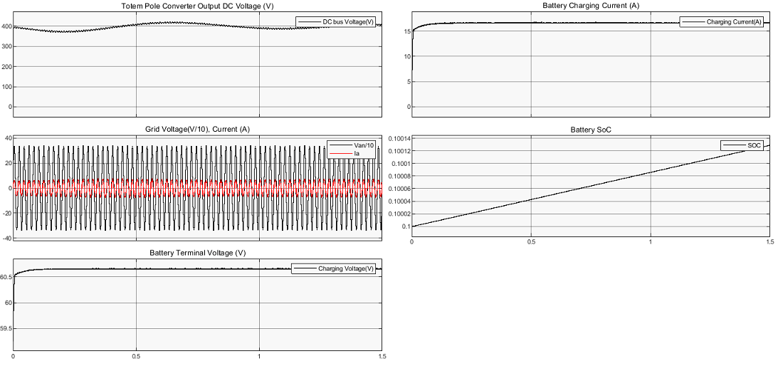
The plot below shows the DC bus voltage, grid current, battery terminal voltage, and charging current for the ideal switching totem pole converter and for the average DC-DC converter. The intermediate capacitor voltage settles at 400V, the grid current is in phase with the grid voltage, and the battery charging is constant at 16.67A.
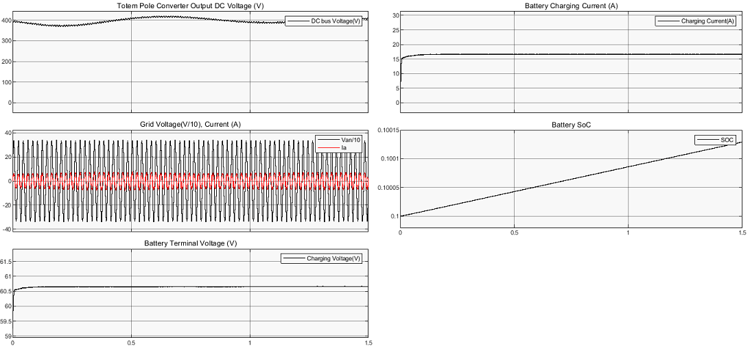
The plot below shows the DC bus voltage, grid current, battery terminal voltage, and charging current for the ideal switching totem pole converter and for the average switching DC-DC converter. The average switching variants capture the switching events of the converters. During the transient state, due to the switching events, the voltage amplitude of the intermediate capacitor swings more than the average variant in the previous plot.
The plot below shows the DC bus voltage, grid current, battery terminal voltage, and charging current for the ideal switching totem pole converter and for the switching DC-DC converter. This variant is mainly intended for loss and efficiency calculation.
Efficiency Calculation
An on-board charger for a two-wheeler vehicles requires a highly efficient converter due to the lack of space for heat dissipation. You can calculate the converter losses to analyze and modify the components responsible for higher losses according to your requirements. In the totem pole converter, the calculation of the losses considers the device losses, such as conduction and switching losses, and the passive loss from the inductor. In the DC-DC converter, the calculation of the losses considers the device losses, such as conduction and switching losses, and the passive losses from the transformer and the inductor.
To estimate the losses, simulate the model in "Switching fidelity" for DC-DC converter until you achieve a steady state. Specify the start and end time at which the losses calculation considers the voltages and current values. These time values must be less than the simulated end time value. Run the script TwoWheelerOnboardChargerLossAnalysis to analyze the losses and calculate the efficiency. This script utilizes the built-in function ee_getPowerLossSummary to calculate individual component losses.
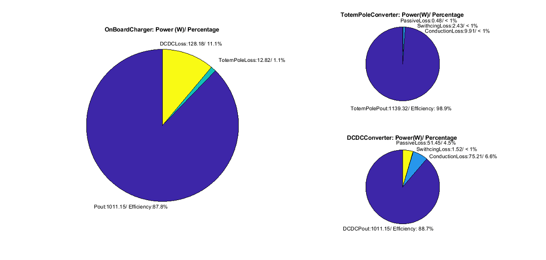
These efficiency values vary according to the components you use in your model.
See Also
Average-Value DC-DC Converter | Four-Quadrant Chopper | MOSFET (Ideal, Switching)