Automatic Tuning of a Helicopter Flight Control System - MATLAB & Simulink
Video Player is loading.
Current Time 0:00
Duration 7:52
Loaded: 0.49%
Stream Type LIVE
Remaining Time 7:52
 
1x
  • Chapters
  • descriptions off, selected
  • captions off, selected
      Video length is 7:52

      Automatic Tuning of a Helicopter Flight Control System

      In this video, you will learn how to tune a multivariable flight control system using the Control System Tuner in Simulink. We will use an example of a helicopter flight control system that includes 21 gains to tune, a challenging task made manageable with the Control System Tuner. The system aims to satisfy four key requirements, which range from tracking setpoint changes, to ensuring strong multivariable gain and phase margins, and limiting the speed of closed-loop system dynamics. The Control System Tuner allows the user to specify tuning goals that reflect these requirements, converting them into an optimization problem to automatically tune the controller parameters.

      Published: 15 Jun 2023
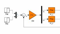
      In this video, you will see how to tune a multivariable fixed structure controller using Control System Tuner. This Simulink model here contains a block representing the helicopter dynamics, as well as blocks representing the helicopter flight control system. There are three PA controller blocks and the 3 by 5 decoupling matrix in the inner loop for stability augmentation. So, in total, we have about 21 gains to tune, which would be pretty difficult to do if we were using any traditional design methods.

      Let's say the control system must satisfy four requirements. The first requirement is to track set point changes in theta, phi, and r, which are the pitch and roll angles and yaw rate with a zero steady state error, 1 second response time, minimum overshoot, and minimum crosscoupling.

      The second and third requirements are to provide strong multivariable gain and phase margins at the plant input and the plant output. Let's say we need about 5 dBs of gain margin and 40 dBs of phase margin at the plant input and output. And the fourth and final requirement is to limit how fast the closed loop system dynamics is so as to not exceed the flexible modes of the helicopter.

      The system here is initialized with default gain values. The PI gains are set to ones and the decoupling matrix elements are all set to zeros. If we run the simulation and look at the results, we will see that the system is unstable with the set of controller gains.

      So let's tune our control system. To do that, we will use the Control System Tuner app. We'll go to the Apps tab and choose the Control System Tuner to launch it. The Control System Tuner lets you tune any control system architecture to meet your design goals. You can tune multiple fixed order, fixed structure, SISO or MIMO control elements distributed over any number of feedback loops. We'll be doing most of the work in the Tuning tab of the app. The steps that we will go through to tune the controllers are set up left to right.

      So we will start with selecting the blocks to tune, which would be the decoupling matrix and the 3 PI controllers. Next, we will add the tuning goals. The first goal is the tracking of step commands with some desired step response characteristics. You want to have a good step response tracking with minimal crosscoupling between the channels. To set this tuning goal, we will use the tracking of the Step Commands option under the Time Domain Requirements. Here, the signals that are inputs are the theta, phi, and r reference inputs. And the corresponding outputs are the theta, phi, and r measurements.

      Next, we will specify what the response should look like. So in that case, we want a first order response with a time constant of 1. And now this number here specifies how much the system can deviate from the first order response. So let's change this to 20%. Now click OK to add this first goal.

      The next goal is the closed loop system having a desirable multivariable stability margins at the plant input. We can do that using the minimum stability margins call. We will set the requirements as phi dB multivariable gain margin and 40 degrees multivariable phase margin.

      With that stability margin goals set up for the plant input, we will repeat the same, but this time, for the plant output. We want the same gain and phase margins as the plant output. So we'll specify that here. Finally, our last goal is to limit how fast the closed loop dynamic should be. To do that, we add the constraint on the closed loop system poles. We want their maximum natural frequency to be below 20 radians per second.

      As we add these tuning goals, we get a plot for each tuning objective, showing us how close we are to meeting it. Here, we can see that we are not meeting all of the goals with the default gain values. We can also specify if a tuning goal is a hard or a soft goal by clicking on the Manage Goals. This designation gives you a way to differentiate the must-have goals from the nice-to-have goals. In this example, we do not have any must-have goals, so we will leave this as is.

      Now we are ready to tune. We just pressed the tune button, and the control system tuner converts the tunable controller parameters from the blocks and the tuning goals into an optimization problem and tunes the 21 gains to try to satisfy all the goals we specified.

      Now let's take a look at the tuning report to see how good the tuning was. The number here shows how close we came to meeting all of the goals. The closer this number is to 1, the better we did in meeting all the goals. If we look through the plots, we see that we improved quite a bit in terms of how close we are to meeting these goals.

      The final step now is to update the block parameters with the tune values. If you go back to the Simulink model, you will see that the block parameters have indeed been updated. If you run the simulation now, we see that we have a fast, stable response with very good decoupling between the channels. In this case, theta is commanded to step at time 0. Phi is commanded to step at 3 seconds. And our is commanded to step at 6 seconds. As we see, the changes in each of the three channels barely cause any effect on the other two channels, which is exactly what we wanted.

      Now if you want to repeat this tuning process quickly, or maybe you want to share your tuning workflow with some of your colleagues so they can repeat your steps, the Control System Tuner has the ability to generate a script that replicates your actions that you performed in the app. Here, from the generated script, you can see the portions of the script where we defined the step tracking requirements, followed by the frequency domain requirements of the gain and phase margins, and, finally, the constraints of the closed loop pole locations.

      The systune command here tunes the controller to satisfy these requirements. Now any time we want to repeat the tuning process, all you can do is just run the script.

      So, in summary, we saw how you can use the Control System Tuner to tune a multivariable fixed structure controller. This app can be used to tune multiple fixed structure, fixed order, SISO or MIMO control elements distributed over any number of feedback loops you could have in your applications.

      View more related videos