LTI System
Use linear time invariant system model object in Simulink
Libraries:
Control System Toolbox
Description
The LTI System block imports linear system model objects into the
Simulink® environment. You specify the LTI model to import in the LTI
system variable parameter. You can import any type of proper linear
time-invariant dynamic system model. If the imported system is a state-space (ss) model, you can specify initial state values in the Initial
states parameter.
Examples
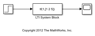
The LTISystemBlockSimulation model shows how to use an LTI System block to simulate the response of a SISO transfer function to a step input.
To specify a model for the LTI System block, set the LTI system variable block parameter to either:
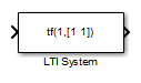
The variable name of an LTI model in the MATLAB® workspace or model workspace, such as
sys.A MATLAB expression that evaluates to an LTI model, such as
tf(1,[1 1]).
For example, you can specify a state-space (ss), zero-pole-gain (zpk), or transfer function (tf) model. You can simulate SISO models or MIMO models, and continuous-time or discrete-time models.
In LTISystemBlockSimulation model, the LTI system variable parameter is a MATLAB expression, tf(1,[1 2 5]), which creates a continuous-time SISO transfer function. If the specified system is a state-space (ss) model, then you can specify initial state values by setting the Initial states parameter.
Simulate the model, and examine the result in the scope.
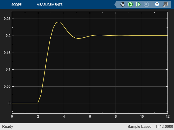
This example simulates the system response to a step input at t = 2 s. Use the LTI System block to import an LTI model object anywhere in your Simulink model to simulate the linear system response to any input.
This model shows how to use an LTI System block to represent a MIMO linear system in Simulink®.
The LTI System block has one input and one output, even when you specify a MIMO model for the block. In that case, the block input and output become vector signals. For instance, the model LTISystemBlockMIMO uses an LTI system block to represent a MIMO plant in a control system.
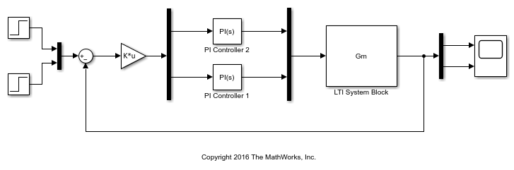
In this model, the LTI System specified in the block is Gm, a 2-output, 2-input transfer function model stored in the model workspace. A Mux block combines the two controller outputs into a vector signal for the LTI System block input. Similarly, a Demux block separates the vector output of the LTI System block into two scalar signals.
Simulate the model, and examine the result in the scope.
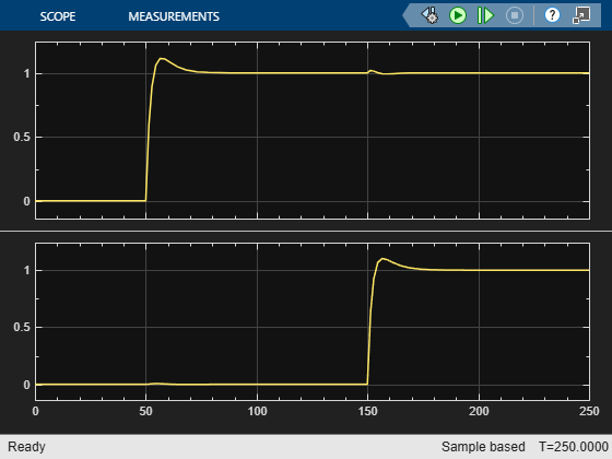
This example simulates a closed-loop system response to a t = 50 s step at the first input and a t = 150 s step at the second input. You can use the LTI system block anywhere you want to insert an LTI system into a Simulink model.