Intersection Movement Assist Using Vehicle-to-Vehicle Communication
This example shows how to model vehicle-to-vehicle (V2V) communication and how to design an Intersection Movement Assist (IMA) safety application using V2V communication. It also shows the effect of channel impairments on the application.
Introduction
V2V communication enables vehicles to exchange information about their states over a wireless network to improve road traffic safety and reduce congestion. By using this technology, each vehicle can get a 360-degree view of the surrounding vehicles. You can use V2V communication to reduce the number of crashes at intersections. This example shows how to model V2V communication using precomputed channel characteristics. It also shows how to design an IMA application using V2V communication. The IMA application in this example evaluates traffic conditions at an intersection and warns the driver of any potential collision threats. Using this example, you can test the IMA application in various test scenarios.
In this example, you:
Explore the test bench model — The test bench model consists of Scenario, Vehicle To Vehicle Communications, Object Tracking, IMA Analysis, and Visualization sections, as well as a Dashboard Panel Display for feedback.
Review characteristics of the V2V communication channel — Plot the precomputed channel characteristics like distance vs. signal-to-noise ratio (SNR), SNR vs. throughput, and distance vs. throughput characteristics of the V2V communication channel for different message transmission ranges and review their effect on message communication between the V2V transmitter and the V2V Receiver.
Model V2V communication — Design a V2V transmitter to generate basic safety message (BSM) and V2V receiver to receive transmitted BSM using the precomputed channel characteristics.
Model the IMA analyzer — Analyze the collision risk for the ego vehicle and generate an IMA warning based on the received BSM.
Simulate the test bench model — Simulate the test scenarios and visualize the results of IMA analysis and the performance of V2V communication for different V2V ranges.
Explore other scenarios — These scenarios test the system under additional conditions.
Explore Test Bench Model
To explore the test bench model, load the intersection movement assist project.
openProject("IntersectionMovementAssist");
Open the test bench model for the Intersection Movement Assist application using V2V communication.
open_system("IntersectionMovementAssistTestBench")

Opening this model runs the helperSLIntersectionMovementAssistSetup function, which initializes the scenario using the drivingScenario object in the base workspace. It runs the default test scenario scenario_01_IMA_Target_Emerges_At_SkewedT_Intersection, which contains an ego vehicle and other vehicles in the Virtual Mcity environment. This function also loads V2XChannelInfo.mat file provided by this example to save the precomputed channel characteristics to base workspace for the range specified. This setup function also configures the analysis parameters and Simulink® bus signals that define the inputs and outputs for the test bench model.
The test bench model contains these sections:
Scenario — Specifies the scenario and actors using Scenario Reader block and converts the actor poses from the ego vehicle coordinates to world coordinates using Vehicle To World block. This section also provides the scene origin for the simulation. The
extractActorInfoMATLAB function block extracts dimensions and class IDs of actors in the scenario and appends it to the bus that specifies data for actor poses.Vehicle To Vehicle Communication — Models the V2V communication. The
V2V Transmittergenerates BSM for each target vehicle using the extracted information for that actor. TheV2V Receiverreceives transmitted BSMs using precomputed channel characteristics. The FIFO queue models a message receive interface that runs on message availability.Object Tracking — Processes and converts the received BSMs into detections using the
processBSMMATLAB function block, and tracks each detection using a Multi-Object Tracker.IMA Analysis — Assesses collision risk for the ego vehicle using the confirmed tracks and ego information and generates an IMA warning.
Visualization — Visualizes the scenario during the simulation and displays IMA analysis results and V2V communication performance.
Dashboard Panel Display — Displays the ego vehicle velocity and IMA warning level.
This example focuses on the V2V communication, IMA analysis and visualization.
Review Characteristics of V2V Communication Channel
The V2V communication represents a message-based communication between the actors that are present in the scenario. The V2V transmitter transmits the messages and the V2V receiver receives the messages. This communication relies on channel characteristics to determine the likelihood of successful message reception.
This example provides the MAT file V2XChannelInfo.mat, which models the precomputed channel characteristics. The example loads the channel characteristics into the base workspace using the helperSLIntersectionMovementAssistSetup function and feeds it to the receiver during simulation. The MAT file contains data about distance vs. SNR and SNR vs. throughput relations. Using this data, the model derives the relation between the throughput and distance.
This example enables you to specify a range to get the precomputed distance vs. SNR data. To specify a range, use the V2VRange name-value argument of the helperSLIntersectionMovementAssistSetup function. The range refers to the distance between the target vehicle and ego vehicle at which the probability of packet detection for the ego vehicle is around 95%.
Plot and compare the channel characteristics for 150 m and 50 m ranges using helperPlotChannelInfo function.
hFig = helperPlotChannelInfo(150,50);

Distance vs SNR — Shows the relation between distance from transmitter to receiver and the SNR for varying ranges. Based on the specified range, the example computes the corresponding distance vs. SNR relation using the offset values provided in the MAT file
V2XChannelInfo.mat.SNR vs Throughput — Shows the throughput performance in frequency-selective fading and additive white Gaussian noise (AWGN) channel. For more details, see the Release 14 V2X Sidelink PSCCH and PSSCH Throughput (LTE Toolbox) example.
Distance vs Throughput — Shows the relation between distance and throughput for the specified range. The throughput refers to expected probability of packet detection. When the range is 150 m, the plot shows that the likelihood of packet detection is nearly 100% up to 150 m and then it gradually decreases until it reaches 0% at around 400 m. Notice that, when the range is 50 m, the probability of packet detection is only close to 100% within the first 50 m, after which it starts decreasing. By a distance of 150 m, packet detection probability with a range of 50 m is already near 0%.
Close the figure.
close(hFig);
Model V2V Communication
This example uses the V2V Transmitter and V2V Receiver subsystems to model the V2V communication. The V2V Transmitter subsystem transmits the BSMs from all target vehicles to the ego vehicle. The V2V Receiver subsystem receives the BSMs at the ego vehicle based on the specified channel characteristics.
Open the V2V Transmitter subsystem.
open_system("IntersectionMovementAssistTestBench/V2V Transmitter")

The V2V Transmitter subsystem implements the transmitters of all the target vehicles in the scenario using the HelperV2VTransmitter System object™. The subsystem reads the actor information and passes it through an inertial navigation system (INS) and global navigation satellite system (GNSS) to apply noise to the actor information. The subsystem also converts the pose information of target vehicles from Cartesian coordinates to geographic coordinates using the scene origin information. Then, the subsystem generates the BSMs for all target vehicles.
A generated BSM contains these attributes for each vehicle [1]:
MsgCount— Sequence number for a stream of messages.TemporaryId— Random device identifier.DSecond— Time at which the position was determined.Latitude— Geographic latitude of the vehicle.Longitude— Geographic longitude of the vehicle.Elevation— Geographic position above or below the reference ellipsoid defined by the World Geodetic System of 1984 (WGS84).PositionalAccuracy— Accuracy of the positional determination.TransmissionState— The current state of the vehicle transmission.Speed— Speed of the vehicle.Heading— Current heading of the vehicle, in degrees clockwise from north.SteeringWheelAngle— Angle of the steering wheel of the driver.AccelerationSet4Way— Acceleration of the vehicle along three directions, and its yaw rotation rates.BrakeSystemStatus— Current brake and system control status.VehicleSize— Length and width of the vehicle.
The Message Send block converts the signal to a Simulink message and delivers to an entity queue. The queues are organized as first-in-first-out (FIFO) queues.
Open V2V Receiver subsystem
open_system("IntersectionMovementAssistTestBench/V2V Receiver")

The V2V Receiver subsystem implements the behavior of the receiver of the ego vehicle using the HelperV2VReceiver System object. The receiver takes the precomputed channel characteristics as a mask parameter and transmitted BSM, scene origin, and the ego information as input. When the transmitter delivers a message in the entity queue, it triggers the V2V Receiver subsystem. For each target vehicle, the receiver computes the distance from that target vehicle to the ego vehicle, and then finds the corresponding throughput using the precomputed channel characteristics. When the throughput is greater than the generated random number, the receiver receives the BSM and stores it in the output bus BSMOut.
Model IMA Analyzer
The IMA Analyzer block, in the IMA Analysis subsystem, assesses the collision risk for the ego vehicle using the tracks that are produced by tracker, and generates an IMA warning.
Open the IMA Analysis subsystem.
open_system("IntersectionMovementAssistTestBench/IMA Analysis")

To generate the IMA warning, the paths for the target and ego vehicles are estimated using their current positions, speeds, and heading angles. The estimated path of each vehicle is a straight line connecting the initial position of the vehicle and its estimated position after 20 seconds. You can adjust the time required for path estimation using the tahead parameter. To assess a collision risk, the IMA Analyzer checks whether the estimated path of the ego vehicle intersects with the estimated paths of the target vehicles. If the estimated ego path intersects with the estimated path of any target vehicle, the IMA Analyzer computes these parameters:
Ego arrival time — Specifies the time required for the ego vehicle to reach the path intersection point.
Time gap — Specifies the absolute difference between the arrival times of the ego vehicle and the target vehicle at the path intersection point.
The IMA Analyzer then compares the ego arrival time and time gap values with their respective predefined thresholds. Based on the results of comparison, the analyzer sets an appropriate level of warning, as shown in this table.

High — Both the ego arrival time and time gap are less than their minimum thresholds. High level of warning specifies higher probability of collision at an intersection. As such, the driver of the ego vehicle must take action to avoid collision.
Moderate — The ego arrival time is less than its minimum threshold, but the time gap is greater than or equal to its minimum threshold. This level of warning specifies that the probability of collision is less if the ego vehicle continues moving in the same direction with the same velocity. Hence, the ego vehicle should pass through the intersection with caution, but no immediate action is required.
Low — The ego arrival time is greater than or equal to its minimum threshold, regardless of the relationship of the time gap to its minimum threshold. This level of warning specifies very low probability of collision. As such, the ego vehicle does not require any immediate action.
Simulate Test Bench Model
Set up and run the IntersectionMovementAssistTestBench simulation model to visualize the IMA analysis results and the performance of the V2V communication.
Configure the IntersectionMovementAssistTestBench model to use the scenario_01_IMA_Target_Emerges_At_SkewedT_Intersection scenario and set the V2V communication range to 150 m.
helperSLIntersectionMovementAssistSetup(scenarioFcnName="scenario_01_IMA_Target_Emerges_At_SkewedT_Intersection",V2VRange=150);
Simulate the model for 1 second and visualize the results.
sim("IntersectionMovementAssistTestBench",StopTime="1");

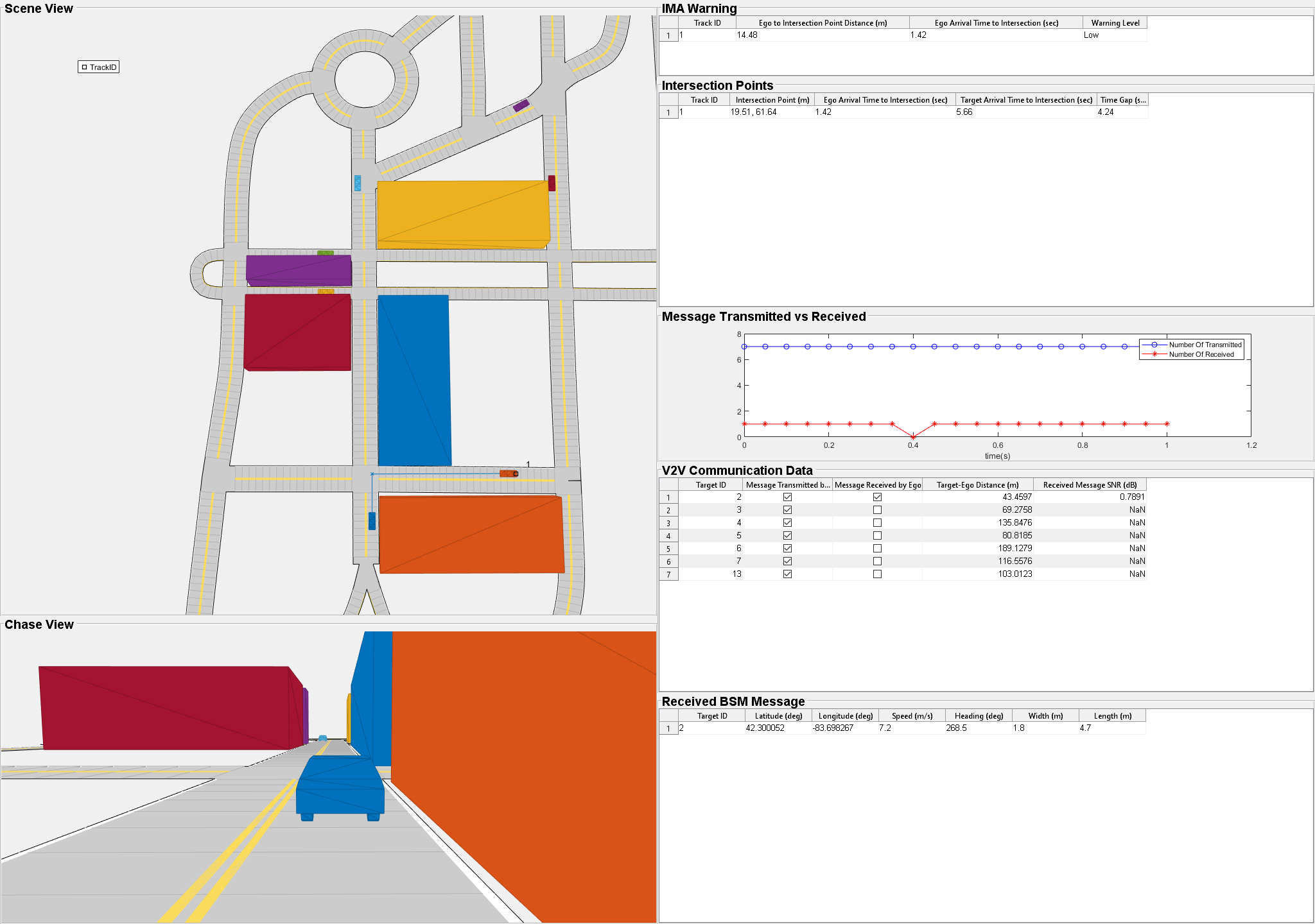
The Visualization subsystem generates a MATLAB figure that displays this information:
Scene View — Displays a bird's-eye-view plot of the scenario that shows the estimated paths of the ego and target vehicles and their intersecting points.
Chase View — Displays a chase view of the scenario, showing the ego vehicle and other target vehicles within the field of view.
IMA Warning — Displays the IMA warning, the ego vehicle arrival time to the intersection point, and the distance between the ego vehicle and the intersection point for the upcoming path intersection point.
Intersection Points — Displays, for each target, a path intersection point, time to arrive at the intersection point, distance from the intersection point, and time gap between that target and the ego vehicle arriving at the intersection point.
Message Transmitted vs Received — Plots the number of transmitted and received messages at each time step.
V2V Communication Data — Displays information about the transmission and reception of BSM and SNR details for each received message.
Received BSM Message — Displays the latitude, longitude, speed, heading, length, and width for each target whose BSM messages are received.
The dashboard displays the IMA warning during the simulation. The color of the IMA warning indicator corresponds to the severity of the collision risk.

Green — No collision risk
Yellow — Low collision risk
Orange — Moderate collision risk
Red — High collision risk
Set the range to 50 m, and run the simulation again to visualize the effects of channel impairments on IMA performance.
helperSLIntersectionMovementAssistSetup(scenarioFcnName="scenario_01_IMA_Target_Emerges_At_SkewedT_Intersection",V2VRange=50);
sim("IntersectionMovementAssistTestBench",StopTime="1");
Notice that when you reduce the range to 50 m, the number of received BSM messages also declines. At the 50 m range, the receiver receives a message for only one target vehicle. In contrast, the receiver received the messages for most of the target vehicles at the 150 m range.
Simulate the complete scenario with a range of 150 m.
helperSLIntersectionMovementAssistSetup(scenarioFcnName="scenario_01_IMA_Target_Emerges_At_SkewedT_Intersection",V2VRange=150);
simout = sim("IntersectionMovementAssistTestBench");

Plot the results.
hFigResults=helperPlotIMAAnalysisResults(simout);

The Ego Arrival Time To Intersection plot shows the arrival time of ego vehicle to the upcoming intersection. If the ego arrival time is greater than the minimum arrival time, then the IMA warning is low. If the ego arrival time is less than the minimum arrival time, then the IMA warning is moderate or high, depending on the time gap.
The Target Arrival Time To Intersection plot shows the arrival time of the target vehicle whose path intersects with the path of the ego vehicle in the upcoming intersection.
The Time Gap plot shows the absolute difference between the arrival times of the ego and target vehicles to the intersection. If the time gap is less than the minimum time gap and ego arrival time is also less than minimum arrival time, then the state of the IMA warning is high.
The IMA Warning plot displays the state of IMA warning at each time step.
Close the figure.
close(hFigResults);
Explore Other Scenarios
In this example, you explored the system behavior for the scenario_01_IMA_Target_Emerges_At_SkewedT_Intersection scenario. This example provides additional scenarios that are compatible with the IntersectionMovementAssistTestBench model.
scenario_01_IMA_Target_Emerges_At_SkewedT_Intersectionscenario_02_IMA_Target_Emerges_At_Oblique_Intersectionscenario_03_IMA_Ego_Emerges_At_T_Intersectionscenario_04_IMA_Ego_Emerges_At_Oblique_Intersectionscenario_05_IMA_Ego_Emerges_At_NarrowT_Intersection
These scenarios have been created using the Driving Scenario Designer app and then exported to scenario files. Examine the comments in each file for more details on the road and vehicles in each scenario. You can configure the IntersectionMovementAssistTestBench and workspace to simulate these scenarios using the helperSLIntersectionMovementAssistSetup function. For example, to configure the simulation for the scenario_02_IMA_Target_Emerges_At_Oblique_Intersection scenario, enter this command.
helperSLIntersectionMovementAssistSetup(scenarioFcnName="scenario_02_IMA_Target_Emerges_At_Oblique_Intersection");
References
[1] SAE International. Dedicated Short Range Communications (DSRC) Message Set Dictionary. J2735_201603. SAE International, issued September 2015; revised March 2016. https://www.sae.org/standards/content/j2735_201603/.
See Also
Blocks
Topics
- Traffic Light Negotiation
- Traffic Light Negotiation with Unreal Engine Visualization
- Traffic Light Negotiation Using Vehicle-to-Everything Communication
- Autonomous Emergency Braking with Sensor Fusion
- Release 14 V2X Sidelink PSCCH and PSSCH Throughput (LTE Toolbox)
- Truck Platooning Using Vehicle-to-Vehicle Communication
- Highway Lane Change
- Highway Lane Following