dsphdl.ChannelSynthesizer
Description
The dsphdl.ChannelSynthesizer
System object™ combines narrowband signals into a multi-channel signal using the polyphase
filter bank technique. The filter bank uses a prototype lowpass filter and is implemented
using a polyphase structure. You can specify the filter coefficients directly or through
design parameters. The System object provides an architecture suitable for HDL code generation and hardware
deployment.
The System object supports real and complex fixed-point inputs.
To combine multiple narrowband signals into a broadband signal:
Create the
dsphdl.ChannelSynthesizerobject and set its properties.Call the object with arguments, as if it were a function.
To learn more about how System objects work, see What Are System Objects?
Note
You can also generate HDL code for this hardware-optimized algorithm, without creating a MATLAB® script, by using the DSP HDL IP Designer app. The app provides the same interface and configuration options as the System object.
Creation
Syntax
Description
ChannelSynthesizer = dsphdl.ChannelSynthesizer
ChannelSynthesizer = dsphdl.ChannelSynthesizer(PropertyName=Value)
Properties
Usage
Syntax
Description
[
combines the narrowband input dataOut,validOut]
= channelsynthesizer(dataIn,validIn,reset)dataIn signals and returns a broadband
signal, dataOut, when validIn is
1 (true) and reset is 0
(false). When reset is 1 (true), the object stops
the current calculation and clears all internal state.
To use this syntax, set the ResetInputPort property to true. For example:
synthesizer = dsphdl.ChannelSynthesizer(...,ResetInputPort=true);
...
[dataOut,validOut] = synthesizer(dataIn,validIn,reset)
Input Arguments
Output Arguments
Object Functions
To use an object function, specify the
System object as the first input argument. For
example, to release system resources of a System object named obj, use
this syntax:
release(obj)
Examples
Create a function that contains a channel synthesizer object and supports HDL code generation.
Create an input sine wave signal with the specified number of frequency bands, frequency vector, and loop count.
numOfFrequencyBands = 8;
frequency = [-250,-180,-120,50,120,175,230,300];
loopCount = 64;
sinewave = dsp.SineWave(ComplexOutput=true, ...
    Frequency=frequency, ...
   SamplesPerFrame=loopCount);
sa = spectrumAnalyzer(ShowLegend=true, ...
    SampleRate=sinewave.SampleRate*numOfFrequencyBands);
Call the function that contains the dsphdl.ChannelSynthesizer object. You can generate HDL code using this function.
function [yOut,validOut] = HDLSynthesizer8(yIn,validIn)
%HDLSynthesizer8
% Combines narrow band signals to broadband signal using the
% |dsphdl.ChannelSynthesizer| System object(TM).

% |yIn| is a fixed-point row vector and |validIn| is a logical scalar value.
% You can generate HDL code from this function.

  persistent synthesizer8;
  coder.extrinsic('tf');
  coder.extrinsic('dsp.Channelizer');

  if isempty(synthesizer8)
    % Use filter coefficients from non-HDL channelizer. You can also
    % provide your own filter coefficients.
    FilterCoefficients = tf(dsp.Channelizer( ...
        NumFrequencyBands=8));
    synthesizer8 = dsphdl.ChannelSynthesizer( ...
        FilterCoefficients=FilterCoefficients);
  end
  [yOut,validOut] = synthesizer8(yIn,validIn);
end

% Copyright 2021-2023 The MathWorks, Inc.
Synthesize the input data by calling the function.
y = zeros(numOfFrequencyBands,loopCount);
validOut = false(loopCount,1);

for i  = 1:10
    x = fi(sinewave(),1,16); % Each column is a sine wave signal
    for j = 1:loopCount
        [y(:,j),validOut(j)] = HDLSynthesizer8(x(j,:),true);
    end
    yValid = y(:,validOut == true);
    sa(yValid(:));
end

The latency of the dsphdl.ChannelSynthesizer object varies with the IFFT length and filter structure.
Create a dsphdl.ChannelSynthesizer object with a direct form transposed filter structure and 16 frequency bands, and then calculate the latency.
synthesizerDT = dsphdl.ChannelSynthesizer(FilterStructure='Direct form transposed');
latencyDT = getLatency(synthesizerDT,16)
latencyDT = 20
Calculate the latency information for dsphdl.ChannelSynthesizer object with a direct form systolic filter structure and 8 frequency bands.
synthesizerDS = dsphdl.ChannelSynthesizer(FilterStructure='Direct form systolic');
latencyDS = getLatency(synthesizerDS,8)
latencyDS = 21
Enable scaling at each stage of the IFFT. The latency does not change.
synthesizerDS.Normalize = true;
latencyDSn = getLatency(synthesizerDS,8)
latencyDSn =
21
Algorithms
The polyphase filter algorithm requires a subfilter for each FFT channel. For more information on the polyphase filter architecture, see the Channelizer (DSP System Toolbox) block reference page.
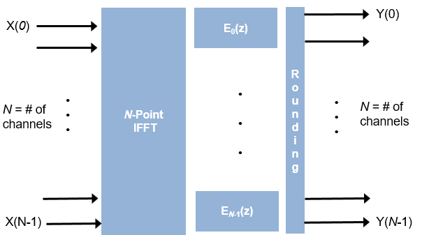
If the FFT length is N, the object implements N subfilters in the hardware. Each subfilter is an FIR filter direct form transposed or direct form systolic with NumCoeffs/N taps. The object casts the output of the subfilters to the specified OutputDataType property by using the rounding and overflow settings you select and then pipelines filter tap in the subfilter to target the DSP sections of an FPGA.
The latency varies with the input size and the filter structure. Use the getLatency
function to find the latency of a particular configuration. Latency is the number of cycles
between the first valid input and the first valid output, assuming that the input is
continuous. The filter coefficients and complex multiplication do not affect the
latency.
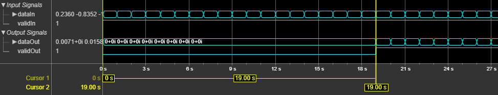
This figure shows the output of the object for a vector input length 8 when you set the
FilterStructure property to 'Direct form
transposed' and with other properties set to default values. The latency of the
object is 19 clock cycles.
This figure shows the output of the object for a vector input of length 8 when you set
the FilterStructure property to 'Direct form
systolic' and with other properties set with default values. The latency of the
object is 31 clock cycles.

References
[1] Harris, Fredric J. Multirate Signal Processing for Communication Systems. Upper Saddle River, N.J: Prentice Hall PTR, 2004.
[2] Harris, Frederic J., Chris Dick, and Michael Rice. "Digital Receivers and Transmitters Using Polyphase Filter Banks for Wireless Communications." IEEE® Transactions on Microwave Theory and Techniques. 51, no 4, (April 2003): 1395–1412. https://doi.org/10.1109/TMTT.2003.809176.