Main Content

Surface

R2026b

Optical surface properties

Since R2026a

    Description

    Add-On Required: This feature requires the Optical Design and Simulation Library for Image Processing Toolbox add-on.

    A Surface object specifies the properties of a surface in an optical system, such as its shape and radius of curvature.

    Creation

    Create a Surface object using these options.

    • Use the addRefractiveSurface object function. Use this function to add at least two refractive surfaces, which constitute a lens element, as the next component of an optical system. You can specify their properties, such as shape, material, and aspheric coefficients, using name-value arguments. When you add two or more surfaces using addRefractiveSurface, you create a LensElement object.

    • Use the addDiaphragm object function. Use this function to add a diaphragm, which contains a surface, as the next component to an optical system. You can specify its properties, such as shape and semi-diameter, using name-value arguments.

    • Use the addMirror object function. Use this function to add a mirror, which contains a surface, as the next component to an optical system. You can specify its properties, such as shape, radius, and aspheric coefficients, using name-value arguments.

    • Use the addImagePlane object function. Use this function to add an image plane, which contains a surface, as the next component to an optical system. You can specify its properties, such as semi-diameter, using name-value arguments.

    • Use the addImageSensor object function. Use this function to add an image sensor, which contains a surface, as the next component to an optical system. You can specify its properties using name-value arguments.

    • Use the optics.surface.Surface function described here. Use this function when you want to create a surface without adding it to the optical system, or modify the properties of a surface already in the system. After creating the object, you can specify the surface properties by modifying the properties of the object.

    Description

    rsurf = optics.surface.Surface creates a Surface object with default properties.

    example

    rsurf = optics.surface.Surface(PropertyName=Value) sets writeable properties using one or more name-value arguments.

    Example: optics.surface.Surface(Radius=10) creates a Surface object representing a surface with a radius of 10.

    Properties

    expand all

    Name of the surface, specified as a scalar or character vector.

    Radius of curvature of the surface, specified as one of these options:

    • Numeric scalar — The radius of curvature applies in both the x- and y-directions.

    • 2-element row vector — Specifies the radius of curvature for a biconic surface, in the form [Rx, Ry], where Rx and Ry are the radii of curvature in the x- and y-directions, respectively.

    Aspheric coefficients describing the aspheric profile of the surface, specified as a 20-element row vector. By default, both even-powered and odd-powered aspheric coefficients are equal to zero, and the surface is spherical. The conic surface shape depends on the magnitude and sign of the conic constant specified by the ConicConstant property.

    Even-powered aspheric coefficients describing the aspheric profile of the surface, specified as a 10-element row vector.

    Conic constant that defines the conic shape of the aspheric surface profile, specified as one of these options:

    • Numeric scalar — The conic constant applies in both the x- and y-directions.

    • 2-element row vector — Specifies the conic constant for a biconic surface, in the form [Kx, Ky], where Kx and Ky are the conic constants in the x- and y-directions, respectively.

    Depending on the value of the conic constant K, the aspheric surface has these conic shapes. For a biconic surface, the conic shape in each direction is determined independently by the corresponding element of ConicConstant.

    ConicConstant (K) ValueConic Shape

    K = 0

    Sphere

    K in range [-1,0]

    Ellipse

    K = -1

    Parabola

    K in range [-inf,-1]

    Hyperbola

    Normalization radius, specified as a positive scalar. The normalization radius is used to non-dimensionalize the higher-order terms in the polynomial describing the aspheric surface.

    Additional Z-sag values on the regular grid, specified as an M-by-N matrix. Units are in millimeters. M is the number of y samples spanning GridYLims, and N is the number of x samples spanning GridXLims.

    The object adds these grid values to the existing surface sag value. Positive values move the surface toward the positive z direction and negative values move the surface toward the negative z direction from the baseline that the object computes using the Radius, ConicConstant, and aspheric term properties in local surface coordinates. The object interpolates grid values using bicubic interpolation and extrapolates values near the edges.

    The element Grid(1,1) corresponds to the corner at (GridYLims(1), GridXLims(1)), which is the minimum y- and minimum x-position of the grid. The element Grid(1,end) corresponds to (GridYLims(1), GridXLims(2)), and Grid(end,end) corresponds to (GridYLims(2), GridXLims(2)), which is the maximum y- and maximum x-position of the grid. Row index increases with y, and column index increases with x.

    Data Types: double

    X-limits of the grid edges in local surface coordinates, specified as a 2-element row vector. Units are in millimeters. The vector is of the form [xmin xmax], where xmin and xmax are the minimum and maximum x-coordinates of the grid, respectively. The second element must be greater than the first.

    By default, the limits are [–sd sd] for circular shapes and [–w/2 w/2] for rectangular shapes, where sd is the semi-diameter and w is the width of the rectangular surface. The object ignores grid values that extend outside the surface shape. Valid regions of the surface not included in these limits use a grid value of 0.

    Data Types: double

    Y-limits of the grid edges in local surface coordinates, specified as a 2-element row vector. Units are in millimeters. The vector is of the form [ymin ymax], where ymin and ymax are the minimum and maximum y-coordinates of the grid, respectively. The second element must be greater than the first.

    By default, the limits are [–sd sd] for circular shapes and [–h/2 h/2] for rectangular shapes, where sd is the semi-diameter and h is the height of the rectangular surface. The object ignores grid values that extend outside the surface shape. Valid regions of the surface not included in these limits use a grid value of 0.

    Data Types: double

    Shape of the surface, specified as one of these options.

    By default, the shape of the surface is circular, with a semi-diameter of 1.

    Optical coating applied to the surface, represented as an opticalCoating object. By default, the coating is applied to the front of the surface. To specify whether to apply the coating to the front, back, or both parts of lens surfaces, use the CoatingSide name-value argument of the addCoating function.

    Position of the first vertex of the surface, specified as a 3-element row vector. The vector is in the form [x y z], where each element is the x-, y-, and z-coordinate in the local coordinate system of the component that contains the surface.

    To learn more about the local component coordinate system, see Coordinate Systems in Optics.

    Tilt angles of the surface, specified as a 3-element row vector. The vector is in the form [θx θy θz], where θx, θy, and θz are tilt angles with respect to the x, y, and z-axes, respectively, of the local coordinate system of the component that contains the surface.

    To learn more about the local component coordinate system, see Coordinate Systems in Optics.

    Note

    The TiltAngles property represents Euler angles. If you specify angles that are multiples of 90 degrees, visually verify the orientation of the optical system. Gimbal lock can occur, in which two of the three rotational axes become aligned. This alignment results in the loss of one degree of freedom, and can lead to ambiguous or unintended orientations.

    Examples

    collapse all

    Create an empty optical system.

    opsys = opticalSystem(Name="Lens");

    Create two lens surfaces using the optics.surface.Surface function. Specify the radius of curvature of the surfaces using the Radius property.

    surf1 = optics.surface.Surface(Radius=2);
    surf2 = optics.surface.Surface(Radius=-2);

    Create a LensElement object, which represents a lens element, using the optics.component.LensElement function. Specify the two lens surfaces to the Surfaces property of the component object. Specify the thickness of the lens as 2.5 millimeters using the Thickness property of the LensElement object.

    lens = optics.component.LensElement(Surfaces=[surf1,surf2],Thickness=2.5)
    lens = 
      LensElement with properties:
    
              Name: [0×0 string]
         Materials: [1×1 opticalMaterial]
         Thickness: 2.5000
          Surfaces: [1×2 optics.surface.Surface]
             Shape: [1×2 optics.shape.Circular]
          Coatings: [0×0 opticalCoating]
          Position: [0 0 0]
        TiltAngles: [0 0 0]


    Add the lens element component to the optical system using the add function.

    add(opsys,lens)

    Display a 2-D visualization of the optical system using the view2d function.

    view2d(opsys)
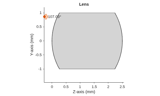
    Figure contains an object of type optics.ui.opticalsystemviewer2d. The chart of type optics.ui.opticalsystemviewer2d has title Lens.

    ans = 
      OpticalSystemViewer2D with properties:
    
                Title: ""
        OpticalSystem: [1×1 opticalSystem]
               Labels: "none"
          FieldPoints: "on"
                 Rays: [0×0 optics.ui.Rays2D]
               Parent: [1×1 Figure]
    
      Show all properties


    Version History

    Introduced in R2026a

    expand all