Main Content

azel2phithetapat

Convert radiation pattern from azimuth-elevation coordinates to phi-theta coordinates

Description

pat_phitheta = azel2phithetapat(pat_azel,az,el) converts the antenna radiation pattern, pat_azel, from azimuth and elevation coordinates to the pattern, pat_phitheta, in phi and theta coordinates. az and el are the azimuth and elevation angles at which the pat_azel values are defined. The pat_phitheta matrix covers theta values from 0 to 180 degrees and phi values from 0 to 360 degrees in one degree increments. The function interpolates the pat_azel matrix to estimate the response of the antenna in a given phi-theta direction.

example

pat_phitheta = azel2phithetapat(pat_azel,az,el,phi,theta) also specifies phi and theta as the grid at which to sample pat_phitheta. To avoid interpolation errors, phi should cover the range [0,180], and theta should cover the range [0,360].

example

pat_phitheta = azel2phithetapat(___,'RotateZ2X',rotpatax) also specifies rotpatax to indicate the boresight direction of the pattern along the x-axis or the z-axis.

example

[pat_phitheta,phi_pat,theta_pat] = azel2phithetapat(___) also returns vectors phi_pat and theta_pat containing the phi and theta angles at which pat_phitheta is sampled.

example

Examples

collapse all

Convert a radiation pattern to φ/θ form, with the φ and θ angles spaced 1 degree apart.

Define the pattern in terms of azimuth and elevation.

az = -180:180;
el = -90:90;
pat_azel = mag2db(repmat(cosd(el)',1,numel(az)));

Convert the pattern to φ/θ space.

pat_phitheta = azel2phithetapat(pat_azel,az,el);

Plot the result of converting a radiation pattern to ϕ/θ space with the ϕ and θ angles spaced 1 degree apart.

The radiation pattern is the cosine of the elevation.

az = -180:180;
el = -90:90;
pat_azel = repmat(cosd(el)',1,numel(az));

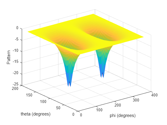
Convert the pattern to ϕ/θ space. Use the returned ϕ and θ angles for plotting.

[pat_phitheta,phi,theta] = azel2phithetapat(pat_azel,az,el);

Plot the result.

H = surf(phi,theta,mag2db(pat_phitheta));
H.LineStyle = 'none';
xlabel('phi (degrees)');
ylabel('theta (degrees)');
zlabel('Pattern');

Figure contains an axes object. The axes object with xlabel phi (degrees), ylabel theta (degrees) contains an object of type surface.

Convert a radiation pattern to the alternate phi-theta coordinates, with the phi and theta angles spaced one degree apart.

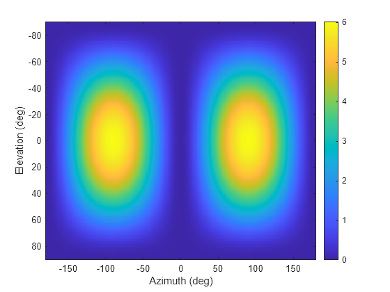
Create a simple radiation pattern in terms of azimuth and elevation. Add an offset to the pattern to suppress taking the logarithm of zero in mag2db.

az = -180:180;
el = -90:90;
pat_azel = mag2db(cosd(el).^2'*sind(az).^2 + 1);

imagesc(az,el,pat_azel)
xlabel('Azimuth (deg)')
ylabel('Elevation (deg)')
colorbar

Figure contains an axes object. The axes object with xlabel Azimuth (deg), ylabel Elevation (deg) contains an object of type image.

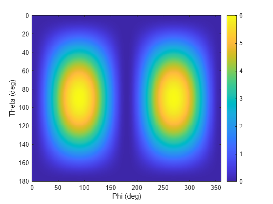
Convert the pattern to phi-theta space.

[pat_phitheta,phi_pat,theta_pat] = azel2phithetapat(pat_azel,az,el,'RotateZ2X',false);
imagesc(phi_pat,theta_pat,pat_phitheta)
xlabel('Phi (deg)')
ylabel('Theta (deg)')
colorbar

Figure contains an axes object. The axes object with xlabel Phi (deg), ylabel Theta (deg) contains an object of type image.

Convert a radiation pattern to ϕ/θ space with ϕ and θ angles spaced 5 degrees apart.

The radiation pattern is the cosine of the elevation.

az = -180:180;
el = -90:90;
pat_azel = repmat(cosd(el)',1,numel(az));

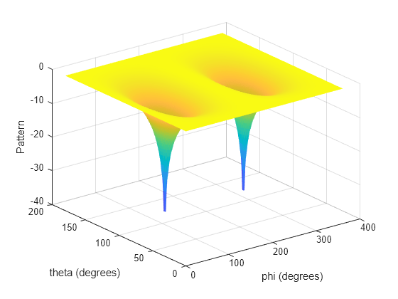
Define the set of ϕ and θ angles at which to sample the pattern. Then, convert the pattern.

phi = 0:5:360;
theta = 0:5:180;
pat_phitheta = azel2phithetapat(pat_azel,az,el,phi,theta);

Plot the result.

H = surf(phi,theta,mag2db(pat_phitheta));
H.LineStyle = 'none';
xlabel('phi (degrees)');
ylabel('theta (degrees)');
zlabel('Pattern');

Figure contains an axes object. The axes object with xlabel phi (degrees), ylabel theta (degrees) contains an object of type surface.

Input Arguments

collapse all

Antenna radiation pattern as a function of azimuth and elevation, specified as a real-valued Q-by-P matrix. pat_azel contains the magnitude pattern. P is the length of the az vector, and Q is the length of the el vector. Units are in dB.

Data Types: double

Azimuth angles at which the pat_azel pattern is sampled, specified as a real-valued length-P vector. Azimuth angles lie between –180 and 180, inclusive. Units are in degrees.

Data Types: double

Elevation angles at which the pat_azel pattern is sampled, specified as a real-valued length-Q vector. Azimuth angles lie between –90 and 90, inclusive. Units are in degrees.

Data Types: double

Phi angles at which the pat_phitheta pattern is sampled, specified as a real-valued length-L vector. Phi angles lie between 0 and 360, inclusive. Units are in degrees.

Data Types: double

Theta angles at which the pat_phitheta pattern is sampled, specified as a real-valued length-M vector. Theta angles lie between 0 and 180, inclusive. Units are in degrees.

Data Types: double

Pattern boresight direction selector, specified as true or false.

  • If rotpatax is true, the pattern boresight is along the x-axis. In this case, the z-axis of phi-theta space is aligned with the x-axis of azimuth and elevation space. The phi angle is defined from the y-axis to the z-axis and the theta angle is defined from the x-axis toward the yz-plane. (See Phi and Theta Angles).

  • If rotpatax is false, the phi angle is defined from the x-axis to the y-axis and the theta angle is defined from the z-axis toward the xy-plane. (See Alternative Definition of Phi and Theta).

Data Types: logical

Output Arguments

collapse all

Antenna radiation pattern in phi-theta coordinates, returned as a real-valued M-by-L matrix. pat_phitheta represents the magnitude pattern. L is the length of the phi_pat vector, and M is the length of the theta_pat vector. Units are in dB.

Phi angles at which the pat_phitheta pattern is sampled, returned as a real-valued length L vector. Units are in degrees.

Theta angles at which the pat_phitheta pattern is sampled, returned as a real-valued length-M vector. Units are in degrees.

More About

collapse all

Azimuth and Elevation Angles

The azimuth angle of a vector is the angle between the x-axis and the orthogonal projection of the vector onto the xy plane. The angle is positive in going from the x axis toward the y axis. Azimuth angles lie between –180 and 180 degrees. The elevation angle is the angle between the vector and its orthogonal projection onto the xy-plane. The angle is positive when going toward the positive z-axis from the xy plane. By default, the boresight direction of an element or array is aligned with the positive x-axis. The boresight direction is the direction of the main lobe of an element or array.

Note

The elevation angle is sometimes defined in the literature as the angle a vector makes with the positive z-axis. The MATLAB® and Phased Array System Toolbox™ products do not use this definition.

This figure illustrates the azimuth angle and elevation angle for a vector shown as a green solid line.

Phi and Theta Angles

The phi angle (φ) is the angle from the positive y-axis to the vector’s orthogonal projection onto the yz plane. The angle is positive toward the positive z-axis. The phi angle is between 0 and 360 degrees. The theta angle (θ) is the angle from the x-axis to the vector itself. The angle is positive toward the yz plane. The theta angle is between 0 and 180 degrees.

The figure illustrates phi and theta for a vector that appears as a green solid line.

The coordinate transformations between φ/θ and az/el are described by the following equations

sinel=sinϕsinθtanaz=cosϕtanθcosθ=coselcosaztanϕ=tanel/sinaz

Alternative Definition of Phi and Theta

The phi angle (φ) is the angle from the positive x-axis to the vector’s orthogonal projection onto the xy plane. The angle is positive toward the positive y-axis. The phi angle is between 0 and 360 degrees. The theta angle (θ) is the angle from the z-axis to the vector itself. The angle is positive toward the xy plane. The theta angle is between 0 and 180 degrees.

The figure illustrates φ and θ for a vector that appears as a green solid line.

ϕ=azθ=90elaz=ϕel=90θ

Extended Capabilities

Version History

Introduced in R2012a
Go to top of page